Deprecated Page - ST-ACR1
Contents
ST-ACR1
Overview
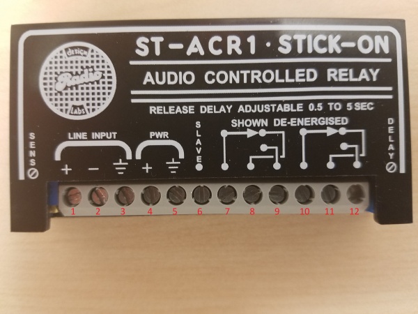
The ST-ACR1 is an audio controlled relay that can be used to change the audio source base on audio input. For example the ST-ACR1 can be used to switch the audio source for a camera when a microphone is activated.
Connections
- 1) Line in Positive
- 2) Line in Negative
- 3) Line in Ground
- 4) Power Positive
- 5) Power Negative
- 6) Slave Terminal
- 7) Relay 1 Output
- 8) Relay 1 Input 1
- 9) Relay 1 Input 2
- 10) Relay 2 Output
- 11) Relay 2 Input 1
- 12) Relay 2 Input 2
Line In
An audio source should be connected to the Line In terminals. When this audio source becomes active, it will trigger the relay.
Power
A 24 Volt DC power supply must be connected to the power terminals.
Relay 1 & 2
Under normal circumstances, the audio from Input 1 will be sent through the output. When the relay is triggered, the audio from Input 2 will be sent through the output. Both relays trigger simultaneously when audio is detected on the Line In.
Example Install: Sim Room/Observation Room
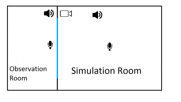
In this example we will be using an audio relay to install a intercom system between an observation room and a simulation room. The observation room has a window in that allows the occupants to watch the simulation in progress.
The observers need to be able to hear what is going on in the simulation room as well as be able to provide feedback and instructions to the people engaged in the simulation. This needs to be accomplished without creating a feedback loop. Additionally, both sources of audio need to be recorded so the recording reflect the interaction between the observers and the simulation participants.
To accomplish these goals, we will need to incorporate an ST-ACR1 into the solution. We will also be using a Preamp to power the microphone and provide line level audio.
The microphone in the observation room and the microphone in the simulation room will each be wired into separate STM1 preamps.
The ACR one will need to be wired as follows
- 1) Positive from observation room preamp output, Positive to speaker in Simulation Room, ST-ACR1 Terminal 9
- 2) Negative from observation room preamp output, Negative to speaker in Simulation Room, B connector with other negatives
- 3) Empty
- 4) Power Supply positive
- 5) Power Supply negative
- 6) Empty
- 7) Positive from simulation room camera audio input
- 8) Positive from simulation room preamp output, ST-ACR1 Terminal 11
- 9) ST-ACR1 Terminal 1
- 10) Positive from observation room speaker
- 11) ST-ACR1 Terminal 8
- 12) Empty

