Difference between revisions of "Unboxing Your Valt POC System"
IVSWikiBlue (talk | contribs) |
IVSWikiBlue (talk | contribs) |
||
| Line 60: | Line 60: | ||
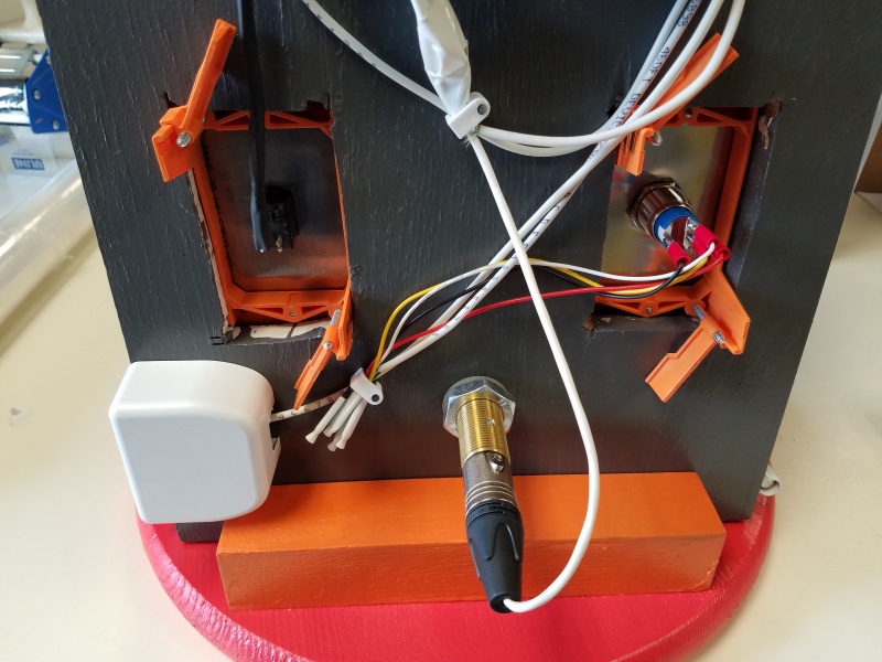
Connect the female XLR tail to the male XLR connector on the back of the microphone. | Connect the female XLR tail to the male XLR connector on the back of the microphone. | ||
| − | [[File:POC17.jpg| | + | |
| + | [[File:POC17.jpg|800x600px]] | ||
Revision as of 08:50, 23 August 2017
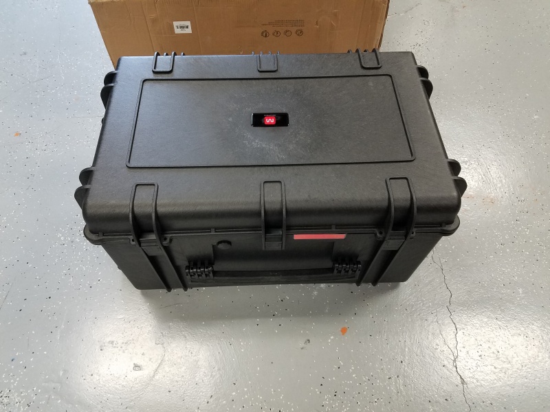
The VALT POC system will be shipped to you in a weather proof hard case. Everything required for you Valt Proof of Concept demonstration will be included in this case.
IVS will only ship the requested equipment for a POC. It may include the following:
- Valt POC Appliance
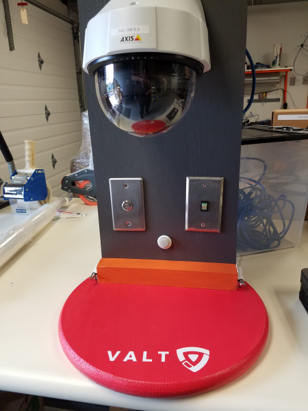
- Valt POC Camera and Stand
- Valt POC Wireless Access Point
The case will be locked with combination locks. Please contact your Valt sales representative for the combination.
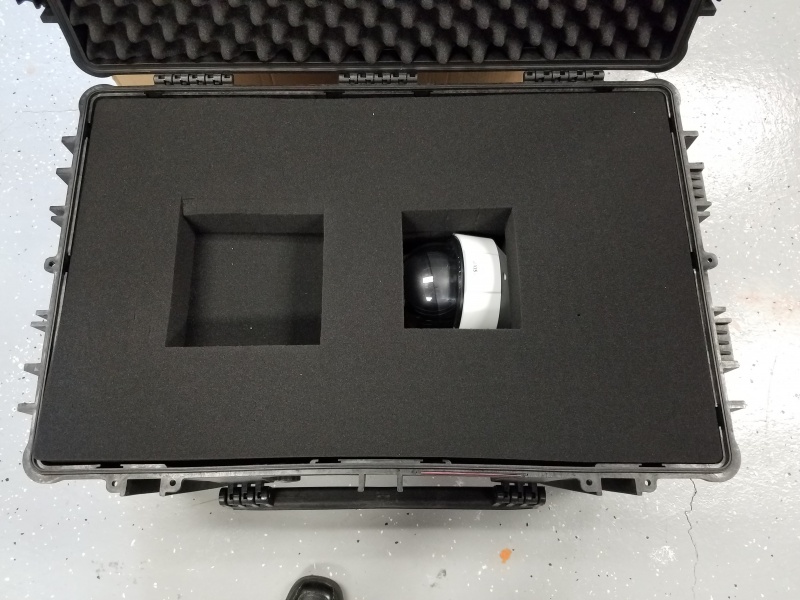
Inside the case, you will find customized foam padding divided into layers. Please make sure to save all padding to use in the return shipment after the proof of concept is complete.
The top layer will contain the Valt POC Appliance (if included) as well as any power cords.
Remove the Valt POC Appliance and set it aside, then remove the top layer of foam.
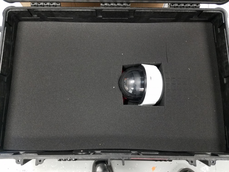
The second layer is just padding.
Remove the second layer of foam.
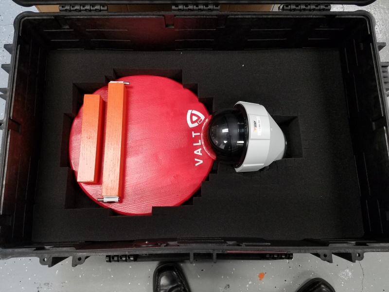
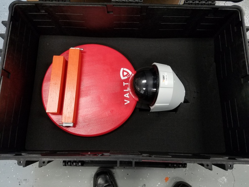
The third layer contains the base for the Valt POC Camera and Stand.
Remove the third layer of foam. There is a small piece of foam between the camera and the stand base.
Remove the Valt POC Camera and Stand base, then remove the fourth layer of foam.
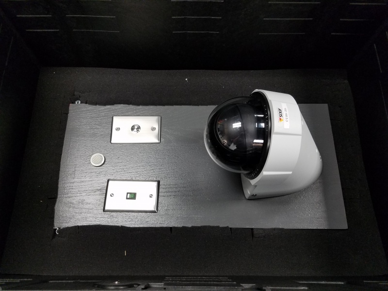
The fifth lay contains the Valt POC Camera and Stand.
Remove the Camera and Stand from the shipping container and then place all the foam back in the container.
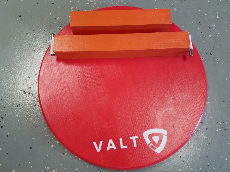
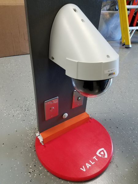
Slide the Valt POC Camera and Stand into the base. The back plane should fit snugly between the two orange braces.
The camera should hang over the open area of the base.
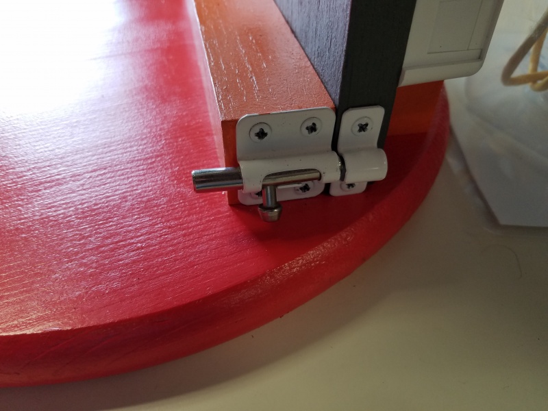
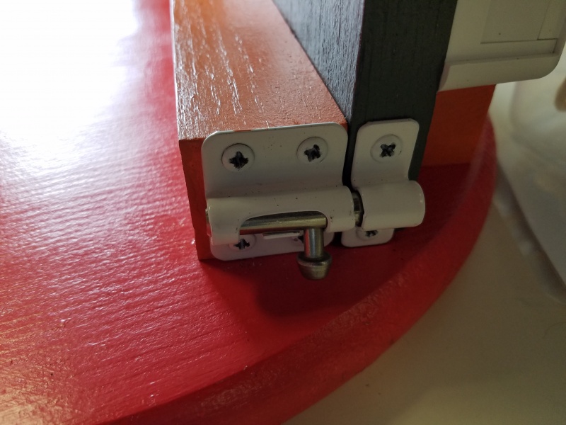
Make sure to line up the brackets on the back plane with the slide locks on the base.
Lock the back plane into place by sliding the the bolts from the base into the brackets on the back plane.
Connect the female XLR tail to the male XLR connector on the back of the microphone.
