Difference between revisions of "M5525 Shure MX202i W/P"
IVSWikiBlue (talk | contribs) (Created page with "==Required Parts And Tools== * Axis M5525 *:60x80px * RDL STM-1 *:60x80px * XLR-F Pigtail *:60x80px * Shure M...") |
IVSWikiBlue (talk | contribs) |
||
| Line 40: | Line 40: | ||
*4 pin XLR-M to XLR-M Adapter (Inside MX202i Box) | *4 pin XLR-M to XLR-M Adapter (Inside MX202i Box) | ||
*:[[File:Shure_Adapter.JPG|60x80px]] | *:[[File:Shure_Adapter.JPG|60x80px]] | ||
| + | |||
| + | |||
| + | ==Connecting the STM-== | ||
| + | |||
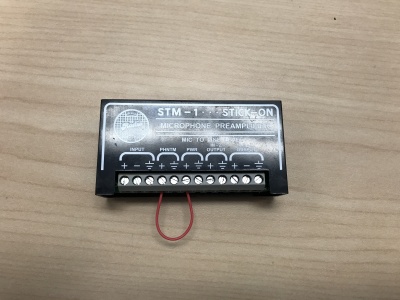
| + | #Connect one end of the 1 inch audio cable to the +PWR terminal and connect the other end of that into the +PHNTM terminal. | ||
| + | #:[[File:Phantom PWR STM.JPG|400x300px]] | ||
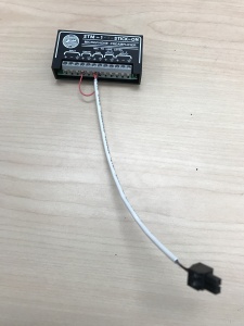
| + | #Connect one of the 4 inch cables to both PWR terminals (Red to +, Black to the other terminal) of the STM-1. Connect the other side to the IO phoenix connector (Red to 2, Black to 1). | ||
| + | #:[[File:STM_Powered_Connected.JPG|400x300px]] | ||
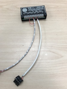
| + | #Connect the second of the 4 inch cables to both HI-Z OUTPUT terminals (Red to +, Black to the other terminal) of the STM-1. Connect the other side to the audio in portion of the audio phoenix connector (Red to +, Black to –). | ||
| + | #:[[File:Wired with power and audio.JPG|400x300px]] | ||
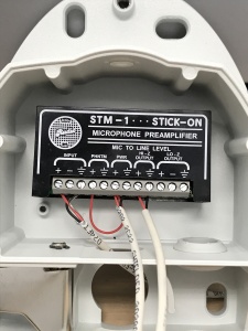
| + | #Connect the audio cable that is intended for your microphone to the input terminals of the STM-1 (Red to +, Black to -, Common to the common terminal). Using the Velcro that comes with the STM-1, attach the STM-1 to the back base of the cameras. | ||
| + | #:[[File:Wired with MIC inside of p5414.JPG|400x300px]] | ||
| + | (NOTE; If there are 2 cameras in the room, duplitcate step 9.1.3 using a long enough cable to get to the 2nd camera. If there are 2 Shure MX202i Microphones, duplicate step 9.1.4.) | ||
Revision as of 10:32, 22 March 2018
Required Parts And Tools
- Axis M5525
- RDL STM-1
- XLR-F Pigtail
- Shure MX202WP/C Microphone
- Wire Stripper
- Anchors and Screws
- 1/2" paddle bit
- 1 blank single gang wall plate
- Toggle Bolts (If mounting to drop ceiling tile)
- Drill bit and drill
- Phillips head drill bit or Phillips head screwdriver
- Small Flat head screwdriver
- Hole Saw
- B Connectors
- Stud Finder
- Cat5/6 Patch Cable (7ft-15ft recommended)
- 22/2 Gauge Wire
- Fish Tape or Glow Rod
- Wind Screen (Inside MX202i Box)
- Rubber Stopper (Inside MX202i Box)
- 4 pin XLR-M to XLR-M Adapter (Inside MX202i Box)
Connecting the STM-
- Connect one end of the 1 inch audio cable to the +PWR terminal and connect the other end of that into the +PHNTM terminal.
- Connect one of the 4 inch cables to both PWR terminals (Red to +, Black to the other terminal) of the STM-1. Connect the other side to the IO phoenix connector (Red to 2, Black to 1).
- Connect the second of the 4 inch cables to both HI-Z OUTPUT terminals (Red to +, Black to the other terminal) of the STM-1. Connect the other side to the audio in portion of the audio phoenix connector (Red to +, Black to –).
- Connect the audio cable that is intended for your microphone to the input terminals of the STM-1 (Red to +, Black to -, Common to the common terminal). Using the Velcro that comes with the STM-1, attach the STM-1 to the back base of the cameras.
(NOTE; If there are 2 cameras in the room, duplitcate step 9.1.3 using a long enough cable to get to the 2nd camera. If there are 2 Shure MX202i Microphones, duplicate step 9.1.4.)


