Difference between revisions of "Installing an Axis P5414/P5415 with a Shure MX202i Microphone"
IVSWikiBlue (talk | contribs) |
IVSWikiBlue (talk | contribs) |
||
| Line 15: | Line 15: | ||
#Cut a 12” length of 18AWG wire and strip wires on both connection ends. | #Cut a 12” length of 18AWG wire and strip wires on both connection ends. | ||
| + | #:[[File:p5414-MX202i1.jpg]] | ||
#Feed red and black wire into the camera power connector end (labelled I/O on the back of the camera) from 5414 camera. Push black twisted wire in the top pinch terminal (numbered 1) and the red wire into the second (numbered 2) pinch terminal, then pull back to ensure that the wires have locked in place. | #Feed red and black wire into the camera power connector end (labelled I/O on the back of the camera) from 5414 camera. Push black twisted wire in the top pinch terminal (numbered 1) and the red wire into the second (numbered 2) pinch terminal, then pull back to ensure that the wires have locked in place. | ||
| + | #:[[File:p5414-MX202i2.jpg]][[File:p5414-MX202i3.jpg]] | ||
#Connect Power to the RDL-STM-1 audio unit at the 24v power input terminals. Be sure to install phantom power jumper as it is needed to power the Shure microphone. The jumper provides phantom power to the left side of the STM-1 and is not needed if using a non-powered microphone solution. | #Connect Power to the RDL-STM-1 audio unit at the 24v power input terminals. Be sure to install phantom power jumper as it is needed to power the Shure microphone. The jumper provides phantom power to the left side of the STM-1 and is not needed if using a non-powered microphone solution. | ||
| + | #:[[File:p5414-MX202i4.jpg]][[File:p5414-MX202i5.jpg]] | ||
#Verify that all connections are firm and all screw down terminals are tight. Then plug connector into camera | #Verify that all connections are firm and all screw down terminals are tight. Then plug connector into camera | ||
| + | #:[[File:p5414-MX202i6.jpg]][[File:p5414-MX202i7.jpg]] | ||
==Connecting Audio to 5414 Camera from RDL STM-1 Audio Interface== | ==Connecting Audio to 5414 Camera from RDL STM-1 Audio Interface== | ||
#Cut a 12” length of 22/2AWG sheilded778 wire and strip wires on both connection ends. | #Cut a 12” length of 22/2AWG sheilded778 wire and strip wires on both connection ends. | ||
| + | #:[[File:p5414-MX202i1.jpg]] | ||
#Twist wire strands together and wire into the HI-Z OUTPUT screw down terminal of the RDL STM-1 as shown on the right below. (red to positive | black to negative) | #Twist wire strands together and wire into the HI-Z OUTPUT screw down terminal of the RDL STM-1 as shown on the right below. (red to positive | black to negative) | ||
| + | #:[[File:p5414-MX202i8.jpg]] | ||
#Twist stripped wire strands together on the opposite end and wire into the camera screw down terminal for audio input (red to positive | black to negative) | #Twist stripped wire strands together on the opposite end and wire into the camera screw down terminal for audio input (red to positive | black to negative) | ||
| + | #:[[File:p5414-MX202i9.jpg]] | ||
#Install Audio connector into the back of the camera as shown below: | #Install Audio connector into the back of the camera as shown below: | ||
| + | #:[[File:p5414-MX202i10.jpg]][[File:p5414-MX202i11.jpg]] | ||
==Connecting Audio to RDL STM-1 Audio Interface from Shure Microphone== | ==Connecting Audio to RDL STM-1 Audio Interface from Shure Microphone== | ||
#Run microphone wire through the wall or above ceiling to the desired location of the microphone. | #Run microphone wire through the wall or above ceiling to the desired location of the microphone. | ||
#Cut 22AWG wire run and strip the ends of the wire for termination into the designated screw down terminals for audio input on the RDL STM-1 Audio Interface. (red to positive | black to negative, ground to ground) | #Cut 22AWG wire run and strip the ends of the wire for termination into the designated screw down terminals for audio input on the RDL STM-1 Audio Interface. (red to positive | black to negative, ground to ground) | ||
| + | #:[[File:p5414-MX202i12.jpg]] | ||
#Connect XLR adapter lead to 22AWG wire that runs back to the STM-1 by twisting the stranded pairs of matching wires together and crimping them with a wire connector. (Red to Red, Black to Black, Ground to Ground) | #Connect XLR adapter lead to 22AWG wire that runs back to the STM-1 by twisting the stranded pairs of matching wires together and crimping them with a wire connector. (Red to Red, Black to Black, Ground to Ground) | ||
| + | #:[[File:p5414-MX202i13.jpg]] | ||
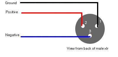
#Connect XLR adapter lead to 22AWG wire that runs back to the STM-1 by following the diagram below. | #Connect XLR adapter lead to 22AWG wire that runs back to the STM-1 by following the diagram below. | ||
#::*Pin 1: Shield / Ground | #::*Pin 1: Shield / Ground | ||
#::*Pin 2: Positive (Red) | #::*Pin 2: Positive (Red) | ||
#::*Pin 3: Negative (Black or White) | #::*Pin 3: Negative (Black or White) | ||
| + | #:[[File:p5414-MX202i14.jpg]][[File:p5414-MX202i15.jpg]] | ||
#Plug XLR Adapter into Shure condenser and then plug that into the Mini 3 Poll plug from Microphone as shown below: | #Plug XLR Adapter into Shure condenser and then plug that into the Mini 3 Poll plug from Microphone as shown below: | ||
| + | #:[[File:p5414-MX202i16.jpg]][[File:p5414-MX202i17.jpg]] | ||
==Installing Microphone== | ==Installing Microphone== | ||
#Use a half inch paddle bit to drill out the mic hole in a standard blank faceplate | #Use a half inch paddle bit to drill out the mic hole in a standard blank faceplate | ||
| + | #:[[File:p5414-MX202i18.jpg]][[File:p5414-MX202i19.jpg]] | ||
#Run the Sure MX202 through your ceiling tile before snaking it through your face place then use anchor bolts to mount faceplate to the ceiling tile as shown below. | #Run the Sure MX202 through your ceiling tile before snaking it through your face place then use anchor bolts to mount faceplate to the ceiling tile as shown below. | ||
| + | #:[[File:p5414-MX202i20.jpg]] | ||
#Install rubber positioning gasket through the face plate and add the pop filter to the end of the sure mic. | #Install rubber positioning gasket through the face plate and add the pop filter to the end of the sure mic. | ||
| + | #:[[File:p5414-MX202i21.jpg]][[File:p5414-MX202i22.jpg]] | ||
#Then wire the XLR adaptor (IVS provided) to the mic 22/2AWG back to the camera and into the imput on the STM1 mic preamplifier | #Then wire the XLR adaptor (IVS provided) to the mic 22/2AWG back to the camera and into the imput on the STM1 mic preamplifier | ||
Revision as of 16:56, 27 October 2016
Contents
Required Parts And Tools
- Shure-MX202i Microphone
- Axis P5414 or P5415 Camera
- RDL STM-1,
- 22/2 Gauge STR OAS CM/CL2 Wire
- XLR to 22/2 Gauge wire Audio Adapter
- Camera Input Connectors
- Small standard screwdriver
- Wire stripping tool
Mounting the Camera
Installing power from the camera to the RDL STM-1 Audio Interface
- Cut a 12” length of 18AWG wire and strip wires on both connection ends.
- Feed red and black wire into the camera power connector end (labelled I/O on the back of the camera) from 5414 camera. Push black twisted wire in the top pinch terminal (numbered 1) and the red wire into the second (numbered 2) pinch terminal, then pull back to ensure that the wires have locked in place.
- Connect Power to the RDL-STM-1 audio unit at the 24v power input terminals. Be sure to install phantom power jumper as it is needed to power the Shure microphone. The jumper provides phantom power to the left side of the STM-1 and is not needed if using a non-powered microphone solution.
- Verify that all connections are firm and all screw down terminals are tight. Then plug connector into camera


Connecting Audio to 5414 Camera from RDL STM-1 Audio Interface
- Cut a 12” length of 22/2AWG sheilded778 wire and strip wires on both connection ends.
- Twist wire strands together and wire into the HI-Z OUTPUT screw down terminal of the RDL STM-1 as shown on the right below. (red to positive | black to negative)
- Twist stripped wire strands together on the opposite end and wire into the camera screw down terminal for audio input (red to positive | black to negative)
- Install Audio connector into the back of the camera as shown below:


Connecting Audio to RDL STM-1 Audio Interface from Shure Microphone
- Run microphone wire through the wall or above ceiling to the desired location of the microphone.
- Cut 22AWG wire run and strip the ends of the wire for termination into the designated screw down terminals for audio input on the RDL STM-1 Audio Interface. (red to positive | black to negative, ground to ground)
- Connect XLR adapter lead to 22AWG wire that runs back to the STM-1 by twisting the stranded pairs of matching wires together and crimping them with a wire connector. (Red to Red, Black to Black, Ground to Ground)
- Connect XLR adapter lead to 22AWG wire that runs back to the STM-1 by following the diagram below.
- Pin 1: Shield / Ground
- Pin 2: Positive (Red)
- Pin 3: Negative (Black or White)
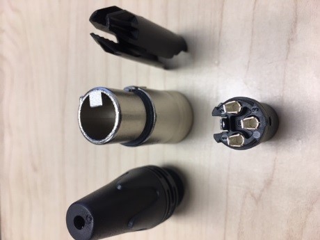
- Plug XLR Adapter into Shure condenser and then plug that into the Mini 3 Poll plug from Microphone as shown below:


Installing Microphone
- Use a half inch paddle bit to drill out the mic hole in a standard blank faceplate
- Run the Sure MX202 through your ceiling tile before snaking it through your face place then use anchor bolts to mount faceplate to the ceiling tile as shown below.
- Install rubber positioning gasket through the face plate and add the pop filter to the end of the sure mic.
- Then wire the XLR adaptor (IVS provided) to the mic 22/2AWG back to the camera and into the imput on the STM1 mic preamplifier


