Difference between revisions of "Privacy Switch"
IVSWikiBlue (talk | contribs) (→Installation) |
IVSWikiBlue (talk | contribs) (→Required Parts and Tools) |
||
| Line 18: | Line 18: | ||
* Single Pole Single Throw Switch | * Single Pole Single Throw Switch | ||
* LED (Instead of an LED you can use an illuminated switch, but it must be independent) | * LED (Instead of an LED you can use an illuminated switch, but it must be independent) | ||
| + | *:[[File:Privacy7.jpg]] | ||
* Mud Ring or Single Gang Box | * Mud Ring or Single Gang Box | ||
* Face Plate | * Face Plate | ||
Revision as of 10:46, 28 December 2016
Contents
Overview
The privacy switch is a customizable solution for placing the cameras connected to the Valt system in privacy mode. The instructions below will outline how to configure a privacy switch that will stay illuminated while the switch is in the off position. Flipping the switch to the on position will extinguish the light and engage privacy mode. The switch and LED are independent and the behavior can be customized. See the variations section at the bottom of this article for more information.
These instruction are written for use with a camera with 4 IO ports. Port 1 and 2 are reserved for use with the Valt Recording Start/Stop button.
Compatible Cameras
The privacy switch should be used with any axis camera with at least one free input and one free output. To use with a camera that does not have 4 I/O ports, you will need to adjust the event rules.
- Axis P5514
- Axis P5515
- Axis P5414
- Axis P5415
- Axis F41
Warning: The privacy switch is not currently compatible with the Axis P3364.
Required Parts and Tools
- Single Pole Single Throw Switch
- LED (Instead of an LED you can use an illuminated switch, but it must be independent)
- Mud Ring or Single Gang Box
- Face Plate
- Wire Cutters/Strippers
- 22/4 solid unshielded plenum

Installation
- Cut a hole in the wall where the privacy switch will be mounted.
- Inset the mud ring into the hole and attach it.
- Run 22/4 from the camera to the hole.
- Strip the outer insulation from both ends of the 22/4.
-
- Strip approximately 1/4 inch of insulation off of each wire in the 22/4 on the camera side
-
- Insert the wires into the IO connector on the camera according to the chart below.
-
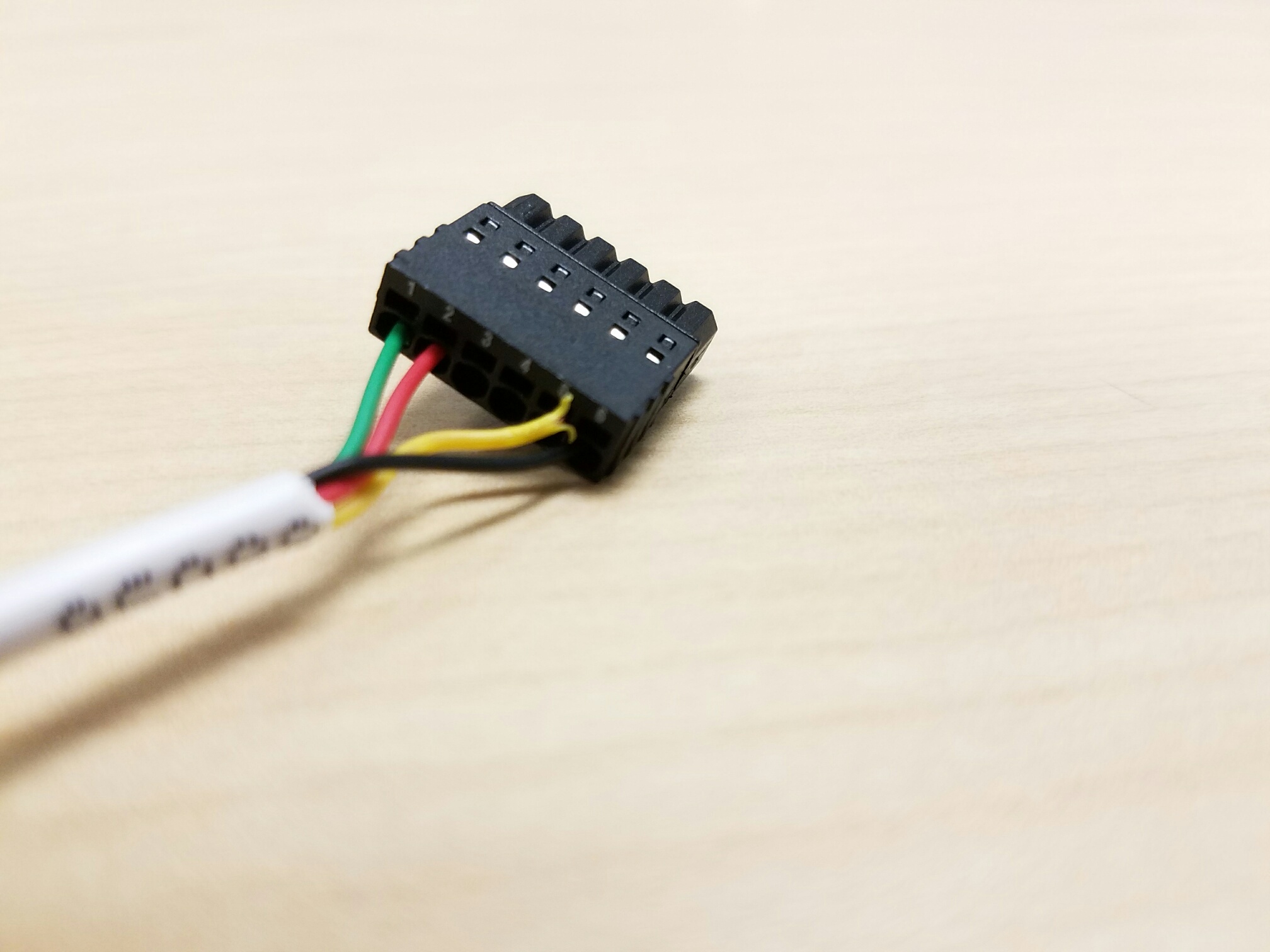
- Pin 1: Green
- Pin 2: Red
- Pin 5: Yellow
- Pin 6: Black
- See the chart at the end of this section for a direct mapping between the switch and I/O connector
-
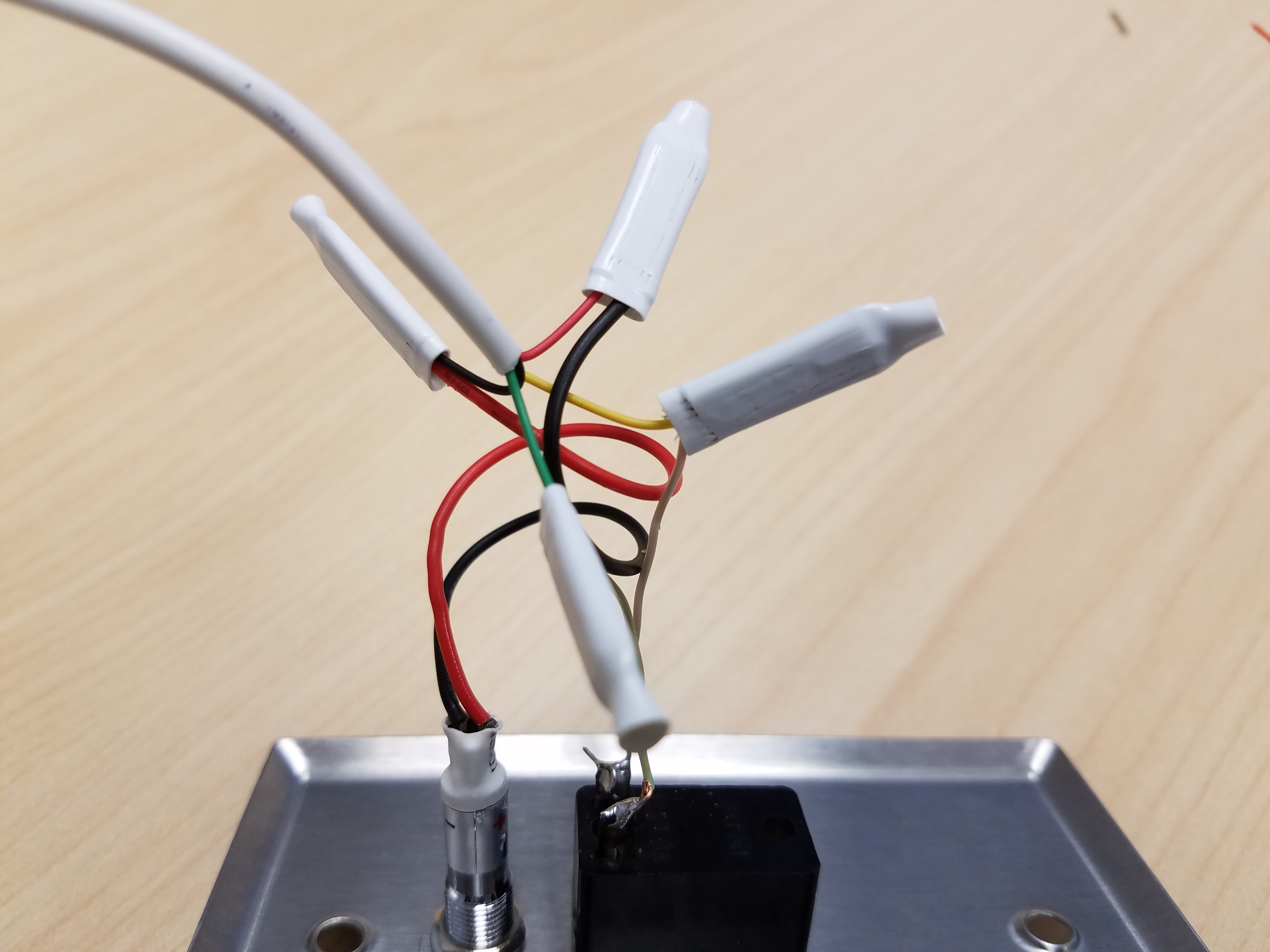
- Strip approximately 1/2 inch of insulation off each wire in the 22/4 on the switch side.
-
- Splice the wires to the switch according to the chart below.
-
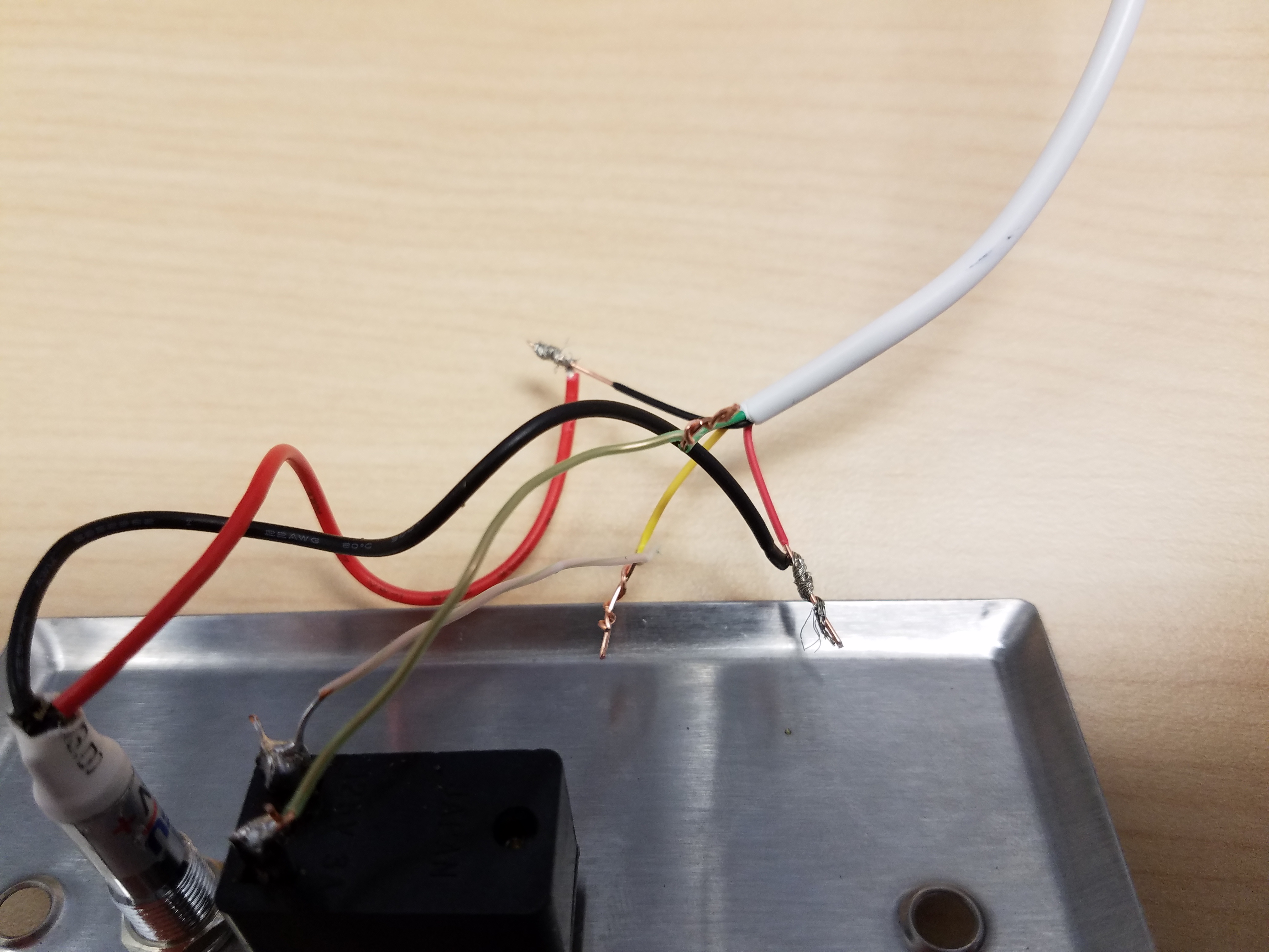
- Green - Switch
- Yellow - Switch
- Red - LED Positive
- Black - LED Ground
- Connections should be soldered, or connected with B connectors
-
-
- Attach the switch to the mud ring.


Wiring Map
I/O Privacy Switch Phoenix Connector Switch Pin 1 + Pin 2 Switch Pin 5 - Pin 6