Difference between revisions of "Observation Room Audio Solution"
IVSWikiBlue (talk | contribs) (Created page with "=Description/Objective= In this example, we will be building 2 sim rooms and 2 observation rooms with live audio. We will have 2 microphones, 2 cameras, and 2 PSP speakers (an...") |
IVSWikiBlue (talk | contribs) (→Connections) |
||
| (11 intermediate revisions by the same user not shown) | |||
| Line 1: | Line 1: | ||
=Description/Objective= | =Description/Objective= | ||
| − | In this example, we will be building 2 sim rooms and 2 observation rooms with live audio. We will have 2 microphones, 2 cameras, and 2 PSP speakers (and/or SHM-1 headphone amps). | + | In this example, we will be building 2 sim rooms and 2 observation rooms with windows and live audio. We will have 2 microphones, 2 cameras, and 2 PSP speakers (and/or SHM-1 headphone amps). |
=Physical Wiring/Line Diagram= | =Physical Wiring/Line Diagram= | ||
| − | + | 2 inputs and 4 outputs will be needed. Use input 1, and outputs 1&2 for the first pair of sim room and observation room; and input 2 and outputs 3&4 for the second pair. When terminating the cables, the mics will go into Orange Inputs; audio lines to the cameras will go into Black Outputs 1&3; audio lines to speakers into Black outputs 2&4. | |
| − | + | {{img | file = ORAS_Config_Line_Diagram.png | width=500px}} | |
=Tesira Software= | =Tesira Software= | ||
==Connections== | ==Connections== | ||
| − | # | + | # If the physical connections are complete, open the Tesira software and start building a configuration. |
| − | # In this configuration | + | # In this configuration use the following blocks: |
#* TesiraFORTE CI block | #* TesiraFORTE CI block | ||
#* Peak Meter x 2 | #* Peak Meter x 2 | ||
| Line 17: | Line 17: | ||
#* Matrix Mixer with at least 2 inputs and 4 outputs, with one extra output | #* Matrix Mixer with at least 2 inputs and 4 outputs, with one extra output | ||
#Connect the blocks as follows: | #Connect the blocks as follows: | ||
| − | #* The Tesira Input block will already be connected to the AEC block, so connect the first peak meter to the Input block also. This will help | + | #* The Tesira Input block will already be connected to the AEC block, so connect the first peak meter to the Input block also. This will help ensure proper levels are set on the preamp. |
#* Connect the AEC block channels 1&2 to the Uber Filters. | #* Connect the AEC block channels 1&2 to the Uber Filters. | ||
| − | #* Send the Uber Filters | + | #* Send the Uber Filters to the Matrix Mixer. |
| − | + | #* Connect output 1-4 from the mixer to port 1-4 on the Tesira Output block AND to the second peak meter. This will ensure the right audio levels are sent to the camera. | |
| − | + | #* Connect the extra output from the Matrix Mixer to the AEC reference. The Automatic Echo Cancellation feature will not be used in this example. However, the AEC reference block cannot be deleted from the configuration. It also will not compile the configuration if any blocks are not connected (including the AEC reference block.) So use the extra output from the mixer as a "dummy output" channel. Do not send any audio to this channel. | |
| − | #* Connect output 1 | ||
| − | #* Connect the extra output from the Matrix Mixer to the AEC reference. | ||
| − | When | + | When this is complete, the file should look something like this: |
| − | [[File: | + | {{img | file = ORAS_Config.png}} |
| + | |||
| + | ==Matrix Mixer== | ||
| + | |||
| + | This is how to send audio to multiple devices without a distribution amp. | ||
| + | |||
| + | [[File:ORAS_Config_with_Mixer.png|link=]] | ||
==Processing Blocks in Tesira== | ==Processing Blocks in Tesira== | ||
| − | + | For further insight about the other processing blocks and settings, refer back to the first configuration example, or click the image below: | |
| + | |||
| + | [[File:Processing_Blocks_Page.png|link=https://ipivs.com/wiki/Simple_Configuration#Processing_Blocks_in_Tesira]] | ||
| + | |||
| + | ==EQ and Compression== | ||
| + | |||
| + | For information on EQ settings, or click the image below: | ||
| + | [[File:EQ_Page.png|link=https://ipivs.com/wiki/EQ_Processing]] | ||
| + | |||
| − | |||
| − | + | For Compression parameters, click the image below: | |
| − | + | [[File:Compression_Page.png|link=https://ipivs.com/wiki/Compression_Settings]] | |
| − | |||
| − | |||
| − | |||
| − | |||
Latest revision as of 10:17, 10 May 2022
Contents
Description/Objective
In this example, we will be building 2 sim rooms and 2 observation rooms with windows and live audio. We will have 2 microphones, 2 cameras, and 2 PSP speakers (and/or SHM-1 headphone amps).
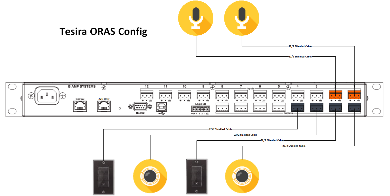
Physical Wiring/Line Diagram
2 inputs and 4 outputs will be needed. Use input 1, and outputs 1&2 for the first pair of sim room and observation room; and input 2 and outputs 3&4 for the second pair. When terminating the cables, the mics will go into Orange Inputs; audio lines to the cameras will go into Black Outputs 1&3; audio lines to speakers into Black outputs 2&4.
Tesira Software
Connections
- If the physical connections are complete, open the Tesira software and start building a configuration.
- In this configuration use the following blocks:
- TesiraFORTE CI block
- Peak Meter x 2
- Uber Filter x 2
- Matrix Mixer with at least 2 inputs and 4 outputs, with one extra output
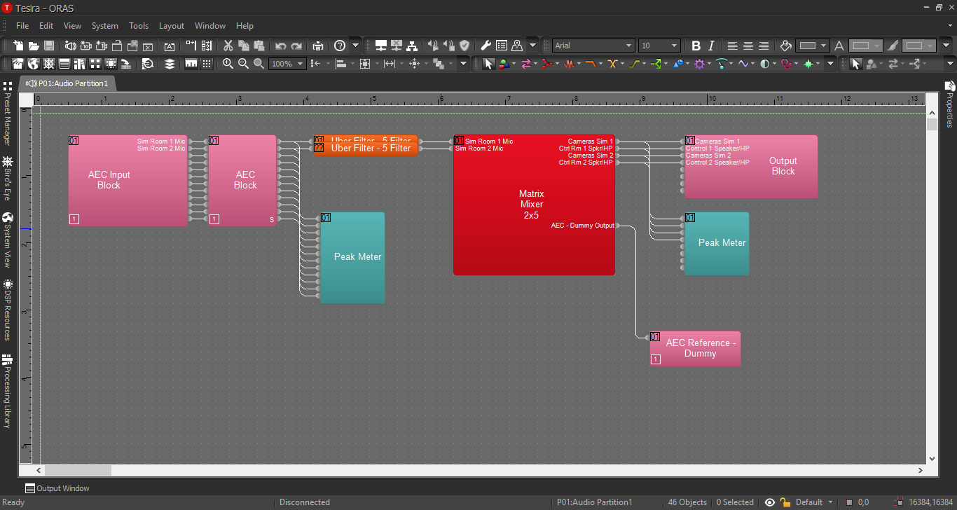
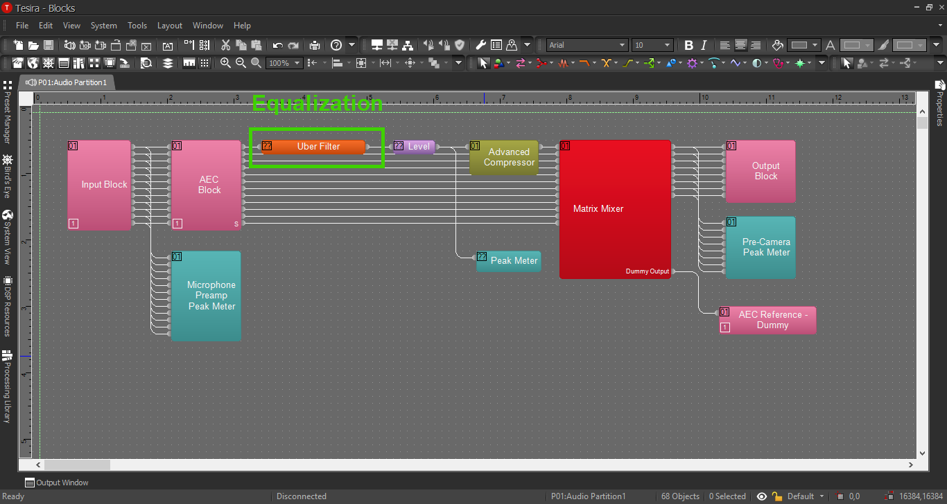
- Connect the blocks as follows:
- The Tesira Input block will already be connected to the AEC block, so connect the first peak meter to the Input block also. This will help ensure proper levels are set on the preamp.
- Connect the AEC block channels 1&2 to the Uber Filters.
- Send the Uber Filters to the Matrix Mixer.
- Connect output 1-4 from the mixer to port 1-4 on the Tesira Output block AND to the second peak meter. This will ensure the right audio levels are sent to the camera.
- Connect the extra output from the Matrix Mixer to the AEC reference. The Automatic Echo Cancellation feature will not be used in this example. However, the AEC reference block cannot be deleted from the configuration. It also will not compile the configuration if any blocks are not connected (including the AEC reference block.) So use the extra output from the mixer as a "dummy output" channel. Do not send any audio to this channel.
When this is complete, the file should look something like this:
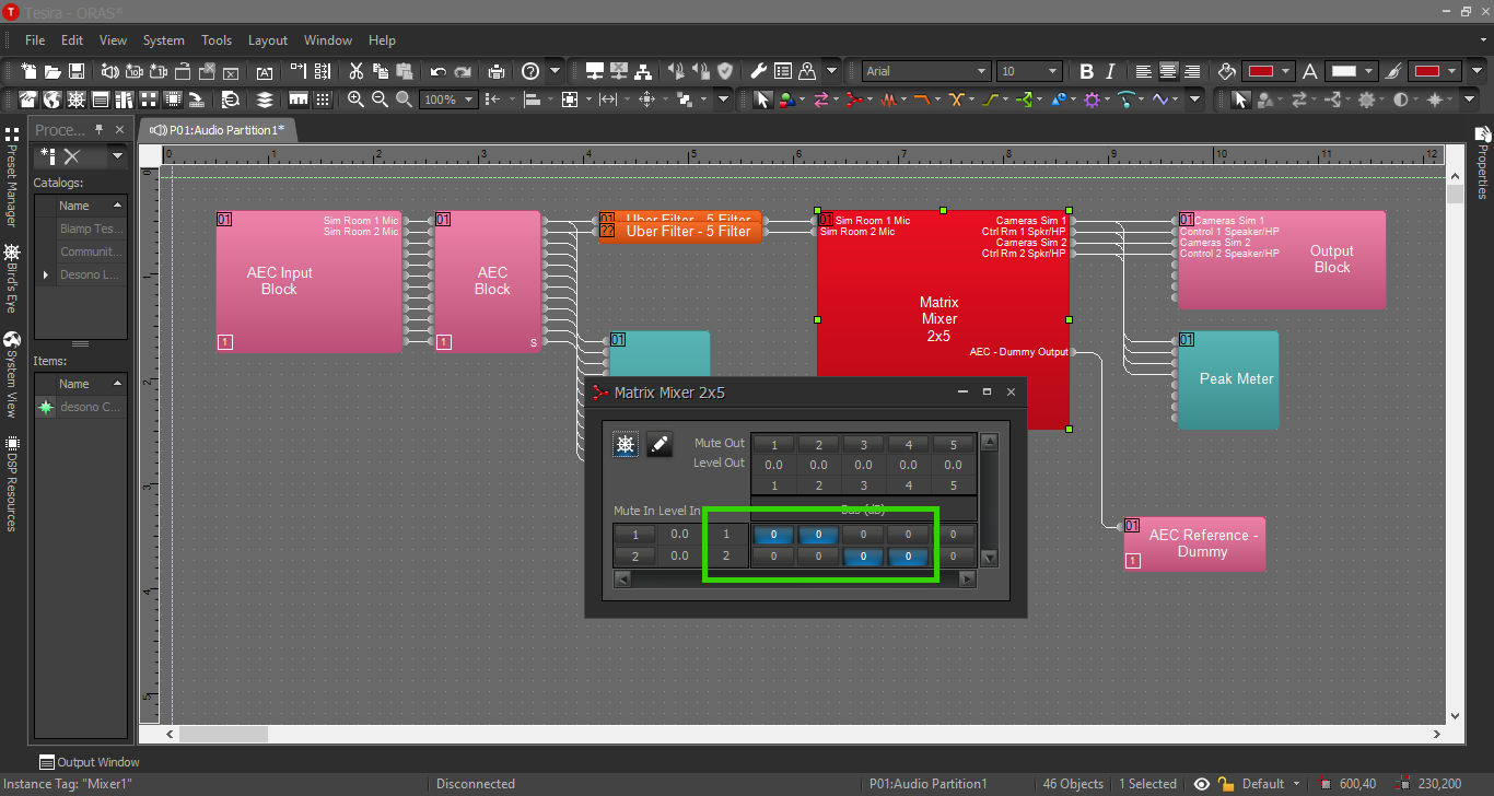
Matrix Mixer
This is how to send audio to multiple devices without a distribution amp.
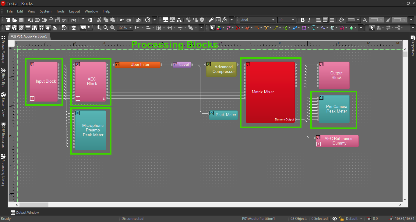
Processing Blocks in Tesira
For further insight about the other processing blocks and settings, refer back to the first configuration example, or click the image below:
EQ and Compression
For information on EQ settings, or click the image below:
For Compression parameters, click the image below:
