Difference between revisions of "Access Control Install"
IVSWikiBlue (talk | contribs) (→Wiring Instructions) |
IVSWikiBlue (talk | contribs) |
||
| (11 intermediate revisions by the same user not shown) | |||
| Line 1: | Line 1: | ||
=Overview= | =Overview= | ||
| − | The | + | The VALT software can work in conjunction with RFID, or pin code, Weigand cards and readers. One of the main advantages to using the card readers is that it gives the users a simple way to start and stop recordings while maintaining a level of security. Cards numbers are assigned to users, so the system knows who started and stopped recordings. To use Weigand readers with the VALT system, you will need Axis A10001 controllers. See controller instructions for specifics regarding wiring readers to the controller. VALT specific installation instructions are detailed below. |
| + | |||
| + | =Wiring Axis A1001 with HID Reader (Weigand)= | ||
| + | ===Tools Needed=== | ||
| + | * Axis A1001 Network Door Controller [[File:Axis A1001.png|60x80px]] | ||
| + | * Small Flat head screw driver | ||
| + | * Phillips head screwdriver | ||
| + | * Wire strippers | ||
| + | * Hole saw | ||
| + | * Small and large anchors | ||
| + | * Small and large screws | ||
| + | * 7ft or 14ft Cat5/6 cable | ||
| + | * HID Multiclass SE RP15 Card Reader [[File:HID READER.png|60x80px]] | ||
| + | * 22/8 cable | ||
| + | * B-Connectors (Optional) | ||
| + | |||
| + | ==Wiring Instructions== | ||
| + | #Remove HID Card Reader and Axis A1001 from their boxes. | ||
| + | #Wire the HID RP15 to the Axis A1001, using the following image as a guideline. Tighten leads with a small flat head screwdriver (if you need longer leads, you can strip Cat5/6 wiring to and connect with B-Connectors to the leads off of the HID Card Reader). | ||
| + | #Ensure the remaining leads are not touching (bare wires). Feel free to cut these as they are not needed. | ||
| + | #Plug the CAT5/6 patch cable into the Axis A1001 to provide power via POE. | ||
| + | |||
| + | :-Wiring with stock wires | ||
| + | ::[[File:WIred A1001.JPG|400x400px]] | ||
| + | :-With 22/8 wires | ||
| + | ::[[File:Wired A1001.JPG|400x400px]] | ||
| + | |||
=A1001 Software Configuration= | =A1001 Software Configuration= | ||
[[File:ac2.jpg|900px]] | [[File:ac2.jpg|900px]] | ||
| − | #) Enter the IP address | + | #) Enter the IP address of the controller, followed by the username and password ('''user''': root '''pw''': whatever was assigned to the controller). |
| − | #) Once logged in the above screen will be displayed. Check the firmware version | + | #) Once logged in, the above screen will be displayed. Check the firmware version. If the reader is not running firmware version 1.50, please upgrade/roll back to that version of firmware. To do this, download [[https://ivs.box.com/shared/static/b1mcduk1ib9hytmhzowdbwvpqm3p4pli.bin|download the 1.50 firmware]], click the '''Upgrade''' button, and browse to the downloaded file. |
| − | #) If the controller is running the proper firmware version click the '''Hardware Configuration''' button | + | #) If the controller is running the proper firmware version click the '''Hardware Configuration''' button. |
[[File:ac3.jpg|900px]] | [[File:ac3.jpg|900px]] | ||
| − | #) Click on '''Start a New Configuration''' as shown above | + | #) Click on '''Start a New Configuration''', as shown above . |
[[File:ac4.jpg|900px]] | [[File:ac4.jpg|900px]] | ||
| − | #) Select '''2 Doors''' then click '''Next''' | + | #) Select '''2 Doors''', then click '''Next'''. |
[[File:ac5.jpg|900px]] | [[File:ac5.jpg|900px]] | ||
| − | #) On Door #1 change to '''Open Circuit = Closed Door''' | + | #) On Door #1, change value to '''Open Circuit = Closed Door'''. |
| − | #) On Door #2 change to '''Open Circuit = Closed Door''' | + | #) On Door #2, change value to '''Open Circuit = Closed Door'''. |
| − | #) Click '''Next''' | + | #) Click '''Next'''. |
[[File:ac6.jpg|900px]] | [[File:ac6.jpg|900px]] | ||
| − | #) On Door #1 change to '''Weigand''' and '''Single LED''' as shown above | + | #) On Door #1, change the value to '''Weigand''' and '''Single LED''', as shown above. |
| − | #) On Door #1 uncheck '''REX''' | + | #) On Door #1, uncheck '''REX'''. |
| − | #) On Door #2 change to '''Weigand''' and '''Single LED''' as shown above | + | #) On Door #2, change the value to '''Weigand''' and '''Single LED''', as shown above. |
| − | #) On Door #2 uncheck '''REX''' | + | #) On Door #2, uncheck '''REX'''. |
| − | #) Click '''Finish''' | + | #) Click '''Finish'''. |
[[File:ac7.jpg|900px]] | [[File:ac7.jpg|900px]] | ||
| − | #) Click on Access Management | + | #) Click on '''Access Management'''. |
| − | #) Under Door #1 click on the '''Edit''' button to the right of '''Reader Entrance''' as shown above | + | #) Under Door #1, click on the '''Edit''' button to the right of '''Reader Entrance''', as shown above. |
[[File:ac8.jpg|900px]] | [[File:ac8.jpg|900px]] | ||
| − | #) Change the name to '''1''' | + | #) Change the name to '''1'''. |
| − | #) Click '''Save''' | + | #) Click '''Save'''. |
[[File:ac9.jpg|900px]] | [[File:ac9.jpg|900px]] | ||
| − | #) Scroll down to Door #2 | + | #) Scroll down to Door #2. |
| − | #) Under Door #2 click on the '''Edit''' button to the right of '''Reader Entrance''' as shown above | + | #) Under Door #2, click on the '''Edit''' button to the right of '''Reader Entrance''', as shown above. |
[[File:ac10.jpg|900px]] | [[File:ac10.jpg|900px]] | ||
| − | #) Change the name to '''2''' | + | #) Change the name to '''2'''. |
| − | #) Click '''Save''' | + | #) Click '''Save'''. |
| − | = | + | =VALT Software Configuration= |
[[File:ac11.jpg|900px]] | [[File:ac11.jpg|900px]] | ||
| − | #) For the last configuration step open the | + | #) For the last configuration step, open the VALT software and log in with admin credentials, then click on the '''Admin''' section. |
| − | #) Click on '''Rooms''' | + | #) Click on '''Rooms'''. |
| − | #) Click on '''Add Device''' | + | #) Click on '''Add Device'''. |
| − | #) Select the Room you want to associate the reader with | + | #) Select the Room you want to associate the reader with. |
| − | #) Name the reader and select '''CardReader''' as device type | + | #) Name the reader, and select '''CardReader''' as device type. |
| − | #) Select the Controller (Door #) the reader is wired to and enter the IP address of the A1001 | + | #) Select the Controller (Door #) the reader is wired to, and enter the IP address of the A1001. |
| − | #) Enter the username and password of the A1001 | + | #) Enter the username and password of the A1001. |
| − | #) Press '''Save''' | + | #) Press '''Save'''. The A1001 should now be set up for use with the VALT software. The last step involves associating card numbers with user accounts. |
| − | == | + | ==VALT User Configuration== |
[[File:ac12.jpg|900px]] | [[File:ac12.jpg|900px]] | ||
| − | #) Log into the | + | #) Log into the VALT software with a user account that has admin rights, then click on the '''Admin''' section |
| − | #) Click on '''Users & Groups''' | + | #) Click on '''Users & Groups'''. |
| − | #) Click on the user you wish to associate a card number with | + | #) Click on the user you wish to associate a card number with. |
| − | #) Click on '''Show advanced settings...''' | + | #) Click on '''Show advanced settings...'''. |
[[File:ac13.jpg|900px]] | [[File:ac13.jpg|900px]] | ||
| − | #) Enter the associated card number into the dialog box as shown above then press '''Save''' | + | #) Enter the associated card number into the dialog box as shown above, then press '''Save'''. |
| − | + | [[Category:Accessories]] | |
| − | |||
| − | |||
| − | |||
| − | |||
| − | |||
| − | |||
| − | |||
| − | |||
| − | |||
| − | |||
| − | |||
| − | |||
| − | |||
| − | |||
Latest revision as of 12:56, 24 March 2025
Contents
Overview
The VALT software can work in conjunction with RFID, or pin code, Weigand cards and readers. One of the main advantages to using the card readers is that it gives the users a simple way to start and stop recordings while maintaining a level of security. Cards numbers are assigned to users, so the system knows who started and stopped recordings. To use Weigand readers with the VALT system, you will need Axis A10001 controllers. See controller instructions for specifics regarding wiring readers to the controller. VALT specific installation instructions are detailed below.
Wiring Axis A1001 with HID Reader (Weigand)
Tools Needed
- Axis A1001 Network Door Controller

- Small Flat head screw driver
- Phillips head screwdriver
- Wire strippers
- Hole saw
- Small and large anchors
- Small and large screws
- 7ft or 14ft Cat5/6 cable
- HID Multiclass SE RP15 Card Reader

- 22/8 cable
- B-Connectors (Optional)
Wiring Instructions
- Remove HID Card Reader and Axis A1001 from their boxes.
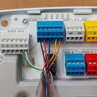
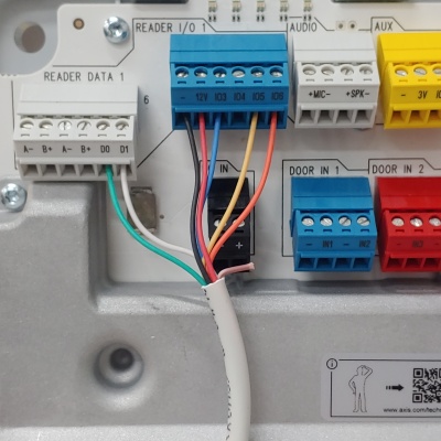
- Wire the HID RP15 to the Axis A1001, using the following image as a guideline. Tighten leads with a small flat head screwdriver (if you need longer leads, you can strip Cat5/6 wiring to and connect with B-Connectors to the leads off of the HID Card Reader).
- Ensure the remaining leads are not touching (bare wires). Feel free to cut these as they are not needed.
- Plug the CAT5/6 patch cable into the Axis A1001 to provide power via POE.
A1001 Software Configuration
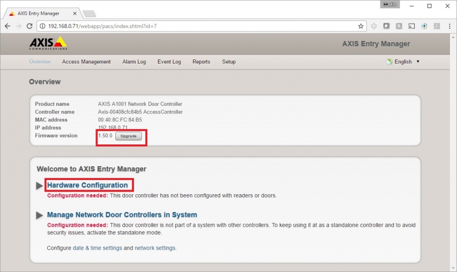
- ) Enter the IP address of the controller, followed by the username and password (user: root pw: whatever was assigned to the controller).
- ) Once logged in, the above screen will be displayed. Check the firmware version. If the reader is not running firmware version 1.50, please upgrade/roll back to that version of firmware. To do this, download [the 1.50 firmware], click the Upgrade button, and browse to the downloaded file.
- ) If the controller is running the proper firmware version click the Hardware Configuration button.
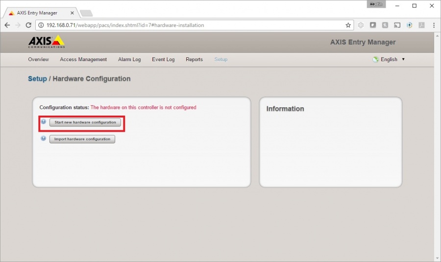
- ) Click on Start a New Configuration, as shown above .
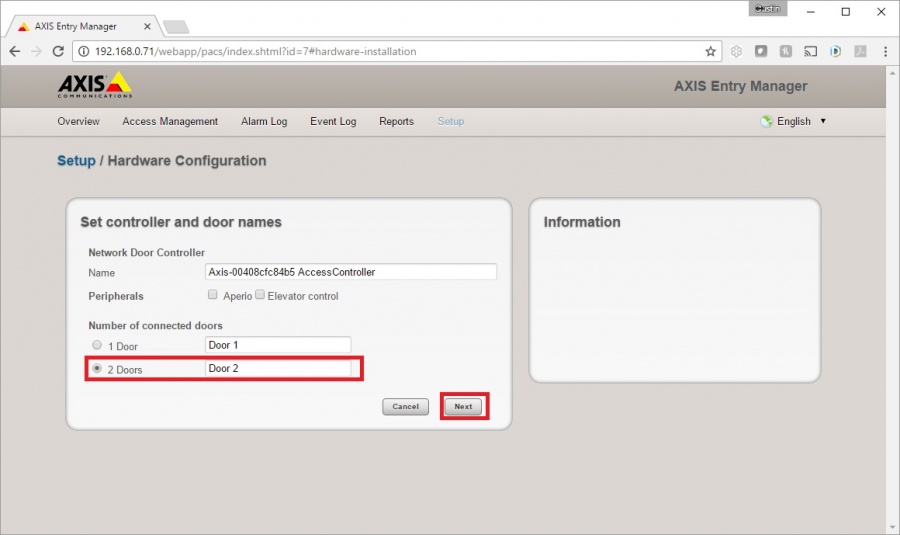
- ) Select 2 Doors, then click Next.
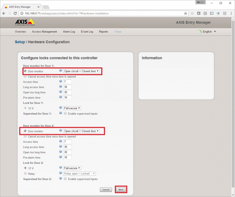
- ) On Door #1, change value to Open Circuit = Closed Door.
- ) On Door #2, change value to Open Circuit = Closed Door.
- ) Click Next.
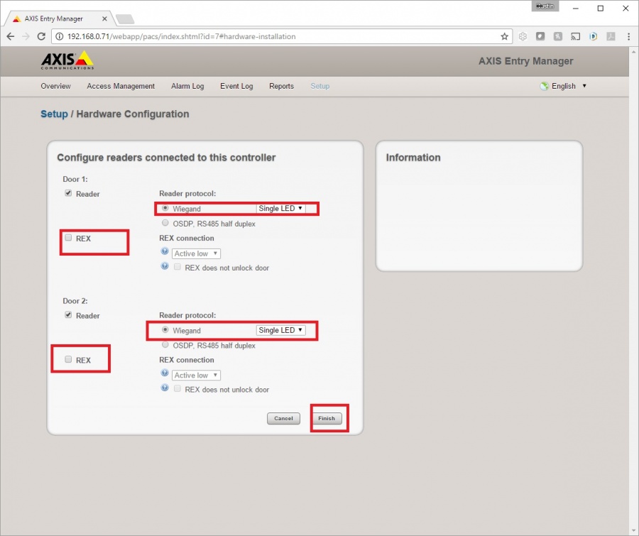
- ) On Door #1, change the value to Weigand and Single LED, as shown above.
- ) On Door #1, uncheck REX.
- ) On Door #2, change the value to Weigand and Single LED, as shown above.
- ) On Door #2, uncheck REX.
- ) Click Finish.
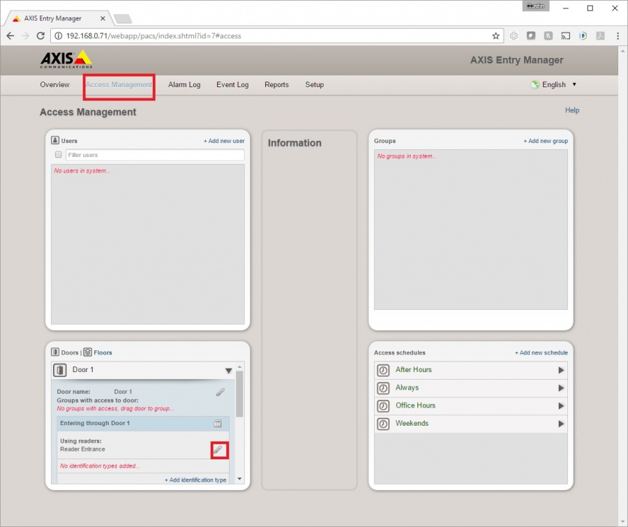
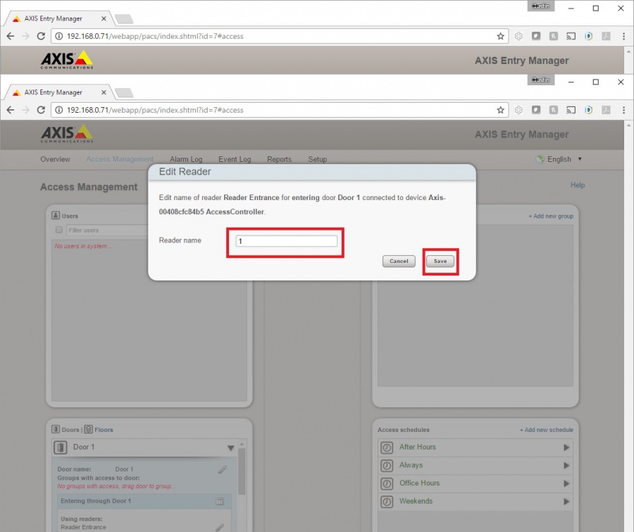
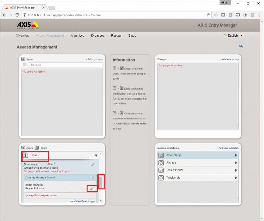
- ) Click on Access Management.
- ) Under Door #1, click on the Edit button to the right of Reader Entrance, as shown above.
- ) Change the name to 1.
- ) Click Save.
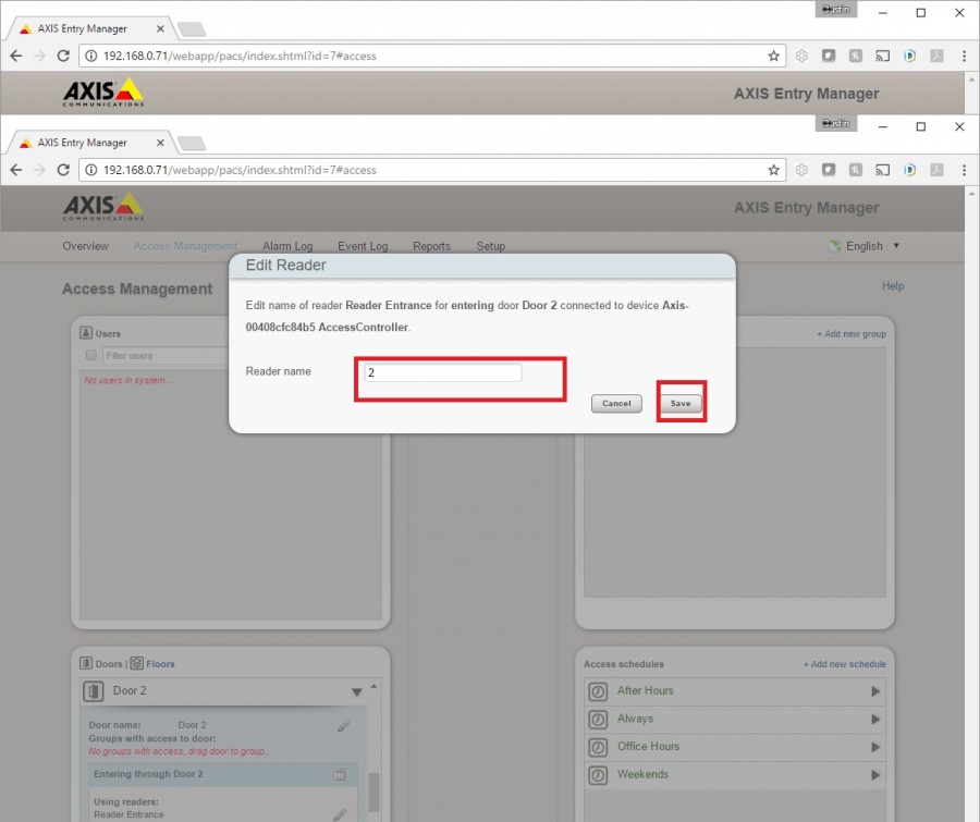
- ) Scroll down to Door #2.
- ) Under Door #2, click on the Edit button to the right of Reader Entrance, as shown above.
- ) Change the name to 2.
- ) Click Save.
VALT Software Configuration
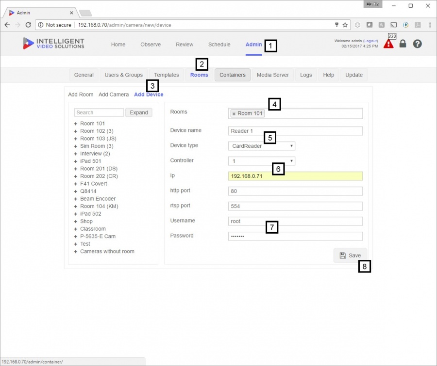
- ) For the last configuration step, open the VALT software and log in with admin credentials, then click on the Admin section.
- ) Click on Rooms.
- ) Click on Add Device.
- ) Select the Room you want to associate the reader with.
- ) Name the reader, and select CardReader as device type.
- ) Select the Controller (Door #) the reader is wired to, and enter the IP address of the A1001.
- ) Enter the username and password of the A1001.
- ) Press Save. The A1001 should now be set up for use with the VALT software. The last step involves associating card numbers with user accounts.
VALT User Configuration
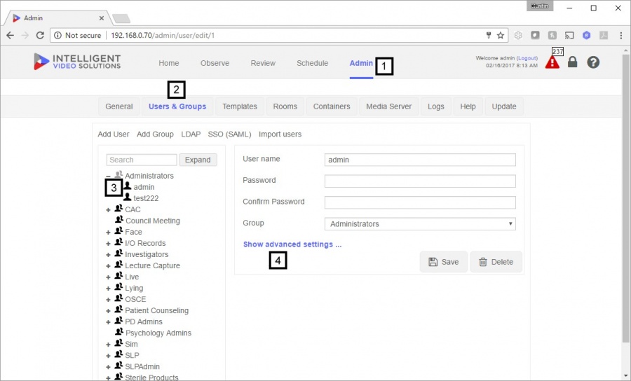
- ) Log into the VALT software with a user account that has admin rights, then click on the Admin section
- ) Click on Users & Groups.
- ) Click on the user you wish to associate a card number with.
- ) Click on Show advanced settings....
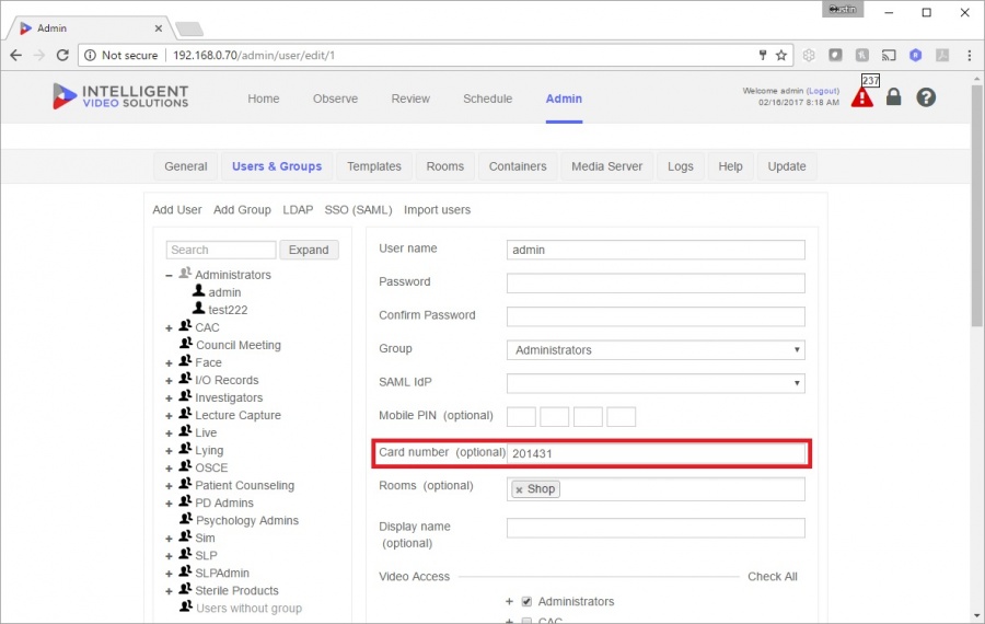
- ) Enter the associated card number into the dialog box as shown above, then press Save.
