Difference between revisions of "Verifact a"
IVSWikiBlue (talk | contribs) |
IVSWikiBlue (talk | contribs) |
||
| (4 intermediate revisions by the same user not shown) | |||
| Line 1: | Line 1: | ||
| − | Start with two pieces of 22/2 and connect | + | Start with two pieces of 22/2 and connect one wire from each to their respective terminals (A for red, B for black), and the ground from both into its terminal (C). |
| − | [[File:VerifactA.jpg| | + | [[File:VerifactA.jpg|450x450px]] |
| − | Take | + | Take the 22/2 wire (red/ground) and connect the ground to IO port 1 and the red to IO port 2. |
| − | |||
| − | + | [[File:IOConnector.JPG|450x450px]] | |
| − | [[File: | ||
| − | Connect both | + | For a 4 PIN IO: |
| + | |||
| + | [[File:4PinAudioConnector.JPG|450x450px]] | ||
| + | |||
| + | Take the other 22/2 cable (black/ground) and connect black to the positive terminal and ground to the negative terminal. | ||
| + | |||
| + | [[File:AudioConnector.JPG|450x450px]] | ||
| + | |||
| + | |||
| + | Connect both connectors into the camera. | ||
Latest revision as of 09:56, 28 February 2020
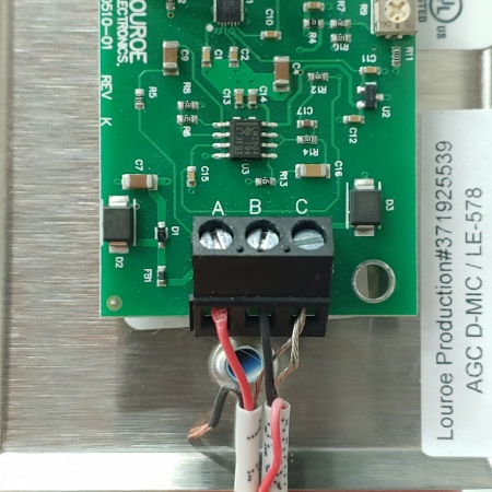
Start with two pieces of 22/2 and connect one wire from each to their respective terminals (A for red, B for black), and the ground from both into its terminal (C).
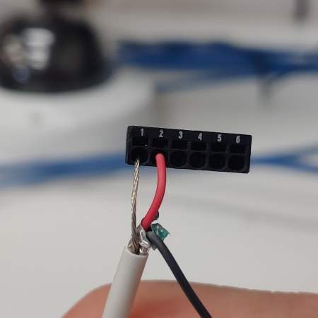
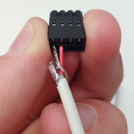
Take the 22/2 wire (red/ground) and connect the ground to IO port 1 and the red to IO port 2.
For a 4 PIN IO:
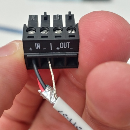
Take the other 22/2 cable (black/ground) and connect black to the positive terminal and ground to the negative terminal.
Connect both connectors into the camera.


