Difference between revisions of "Privacy Button 2020-Present"
IVSWikiBlue (talk | contribs) (→Set Privacy Location for PTZ Camera) |
IVSWikiBlue (talk | contribs) |
||
| (24 intermediate revisions by the same user not shown) | |||
| Line 1: | Line 1: | ||
| − | = | + | {{Article - Manual | content = |
| − | |||
| + | {{:VALT Privacy Button}} | ||
| − | + | {{hr}} | |
| − | |||
| − | |||
| − | |||
=Compatible Cameras and Wire Diagrams= | =Compatible Cameras and Wire Diagrams= | ||
| − | The privacy switch should be usable with any AXIS camera with at least one free input and one free output. The camera must be running firmware version 5.50 or higher. | + | The privacy switch should be usable with any AXIS camera with at least <b>one free input</b> and <b>one free output</b>. The camera must be running firmware version 5.50 or higher. |
| − | |||
| − | |||
| − | |||
| − | |||
| − | |||
| − | |||
| − | [[ | + | {{Dashboard Row | content = |
| + | {{Dashboard Widget with Title | min-width = 250px | title = Cameras with Diagrams | background-color = #FFCB1C | content = | ||
| + | * [[Media:P3235_and_New_Privacy_Switch.png | Axis P3235-LVE]] | ||
| + | * [[Media:P3245_and_New_Privacy_Switch.png | Axis P3245]] | ||
| + | * [[Media:P3245_and_New_Privacy_Switch.png | Axis P3265]] | ||
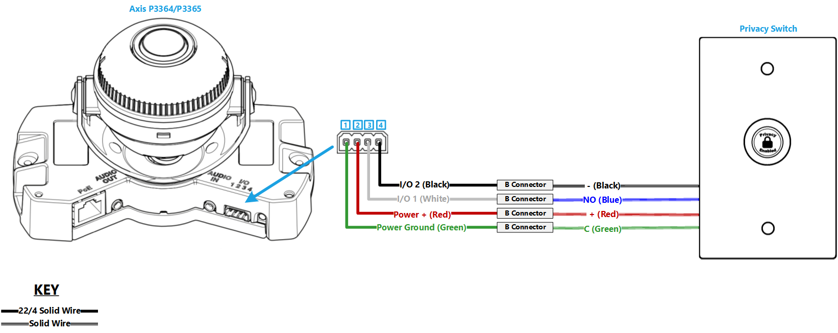
| + | * [[Media:P3364-P3365_and_New_Privacy_Switch.png | Axis P3364/P3365*]] | ||
| + | * [[Media:P3374-P3375_and_New_Privacy_Switch.png | Axis P3374-V/P3375-V*]] | ||
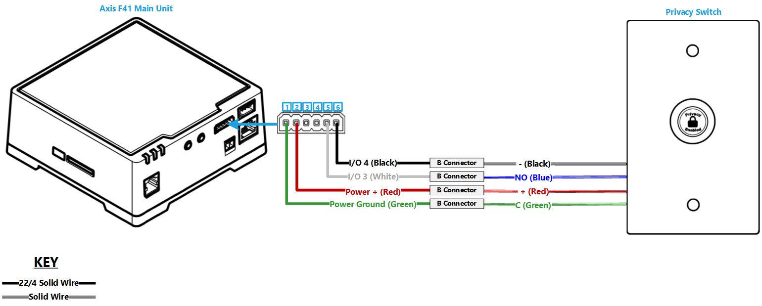
| + | * [[Media:F41_and_New_Privacy_Switch.png | Axis F41 or F91]] | ||
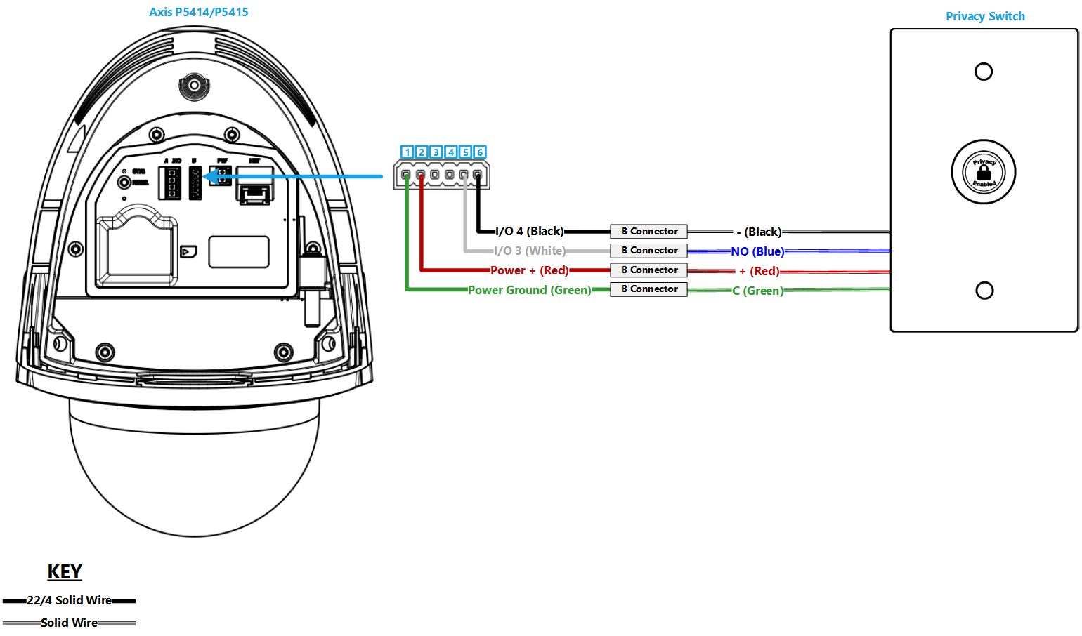
| + | * [[Media:P5414-P5415_and_New_Privacy_Switch.png | Axis P5414-E/P5415-E]] | ||
| + | * [[Media:M5525_and_New_Privacy_Switch.png | Axis M5525 or 5526]] | ||
| + | * [[Media:P5635_and_New_Privacy_Switch.png | Axis P5635-E MK II]] | ||
| + | * [[Media:P5655_and_New_Privacy_Switch.png | Axis P5655]] | ||
| + | * [[Media:Q8414_and_New_Privacy_Switch.png | Axis Q8414-LVS*]] | ||
| + | }} | ||
| − | + | {{Dashboard Widget with Title | min-width = 250px | title = Cameras without Diagrams | content = | |
| + | * Axis P1364/65 | ||
| + | * Axis P3301 | ||
| + | * Axis P3304 | ||
| + | * Axis Q3504/05 MK II | ||
| + | * Axis Q3518 | ||
| + | * Axis P3935-LR | ||
| + | }} | ||
| + | }} | ||
| − | |||
| − | + | {{Aside | content = * These cameras can only be used with a single ancillary device <em>(ie: Button or privacy switch)</em>. To use these with a camera that does not have 4 I/O ports, you will need to adjust the event rules.}} | |
| − | |||
| − | + | {{Top of Page}} | |
| − | + | {{hr}} | |
| − | + | <!-- | |
| − | + | {{Float | content = {{img | file = Privacy Button On.png | width=150px}} }} | |
| − | + | =Installation= | |
| − | + | {{Manual lvl 2 | title = Required Parts and Tools | content = | |
| − | |||
| − | |||
| − | |||
| − | |||
| − | |||
| − | |||
| − | |||
| − | |||
| − | |||
| − | |||
| − | |||
| − | |||
| − | |||
| − | =Required Parts and Tools | ||
| − | |||
* VALT Privacy Switch and Face Plate | * VALT Privacy Switch and Face Plate | ||
* Mud Ring or Single Gang Box | * Mud Ring or Single Gang Box | ||
| Line 55: | Line 50: | ||
* Jab Saw (used to cut hole) | * Jab Saw (used to cut hole) | ||
* Wire fishing poles or tape | * Wire fishing poles or tape | ||
| + | }} | ||
| − | = | + | {{hr - 2}} |
| + | |||
| + | {{Manual lvl 2 | title = Instructions | content = | ||
# Determine if the button will be mounted outside the entrance of the room or at a specified location in the room. | # Determine if the button will be mounted outside the entrance of the room or at a specified location in the room. | ||
# Using a stud finder, scan the mounting location to ensure the device is not mounted on a stud. | # Using a stud finder, scan the mounting location to ensure the device is not mounted on a stud. | ||
# Cut a hole into the drywall, large enough to fit the mud ring into it securely. | # Cut a hole into the drywall, large enough to fit the mud ring into it securely. | ||
| − | #: | + | #: {{img | file = VerifactDring.JPG | width=170px}} |
# Cut a hole in the wall where the privacy switch will be mounted. | # Cut a hole in the wall where the privacy switch will be mounted. | ||
# Insert the mud ring into the hole, and attach it. | # Insert the mud ring into the hole, and attach it. | ||
# Run 22/4 from the camera to the hole. | # Run 22/4 from the camera to the hole. | ||
# Strip the outer insulation from both ends of the 22/4. | # Strip the outer insulation from both ends of the 22/4. | ||
| − | #: | + | #: {{img | file = Privacy1.jpg | width=375px}} |
# Strip approximately 1/4 inch of insulation off of each wire in the 22/4 on the camera side | # Strip approximately 1/4 inch of insulation off of each wire in the 22/4 on the camera side | ||
| − | #: | + | #: {{img | file = Privacy2.jpg | width=375px}} |
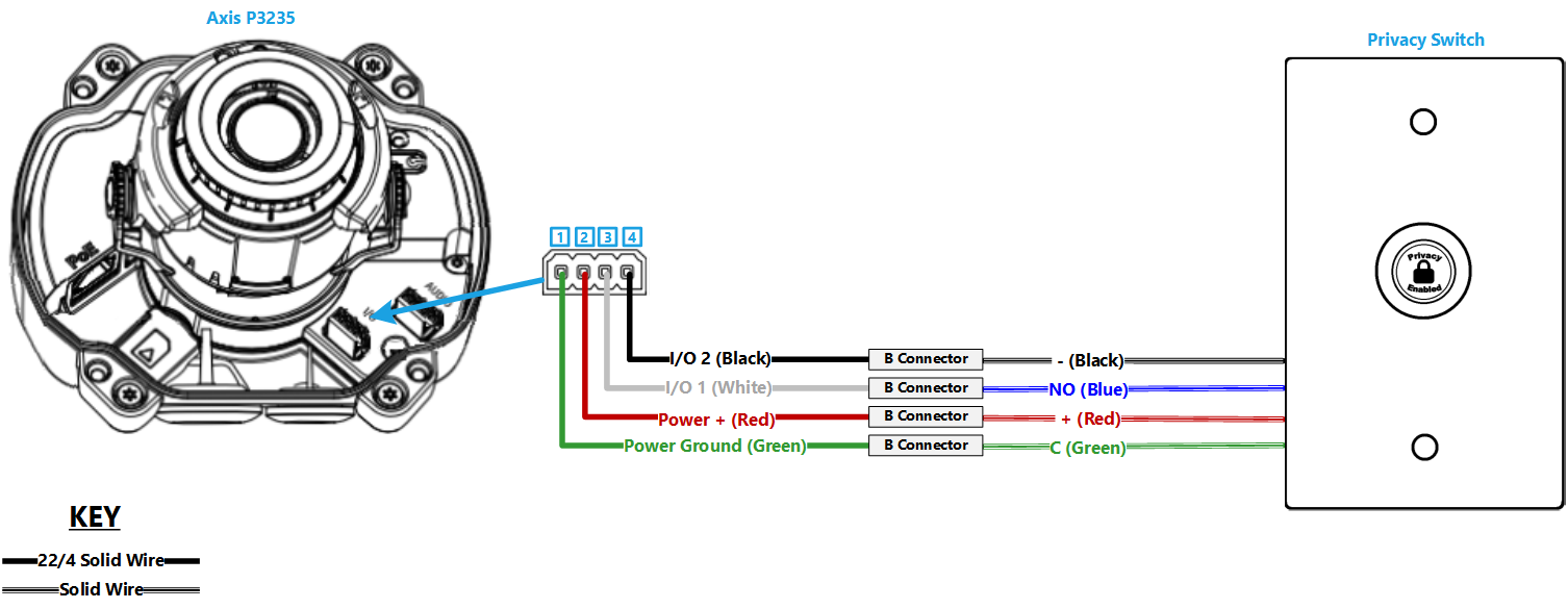
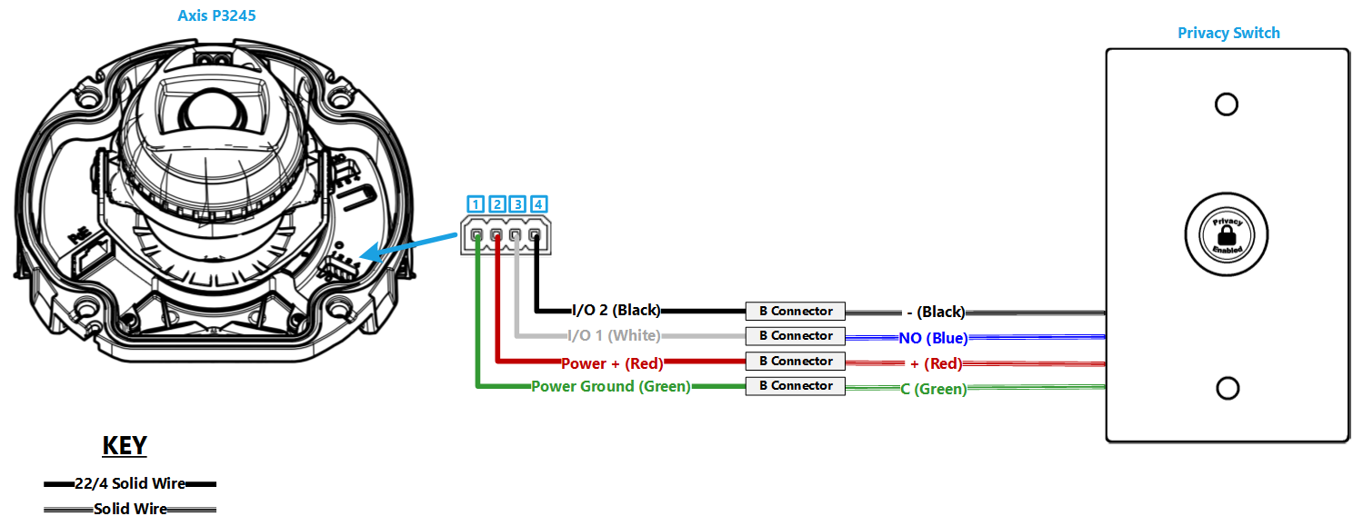
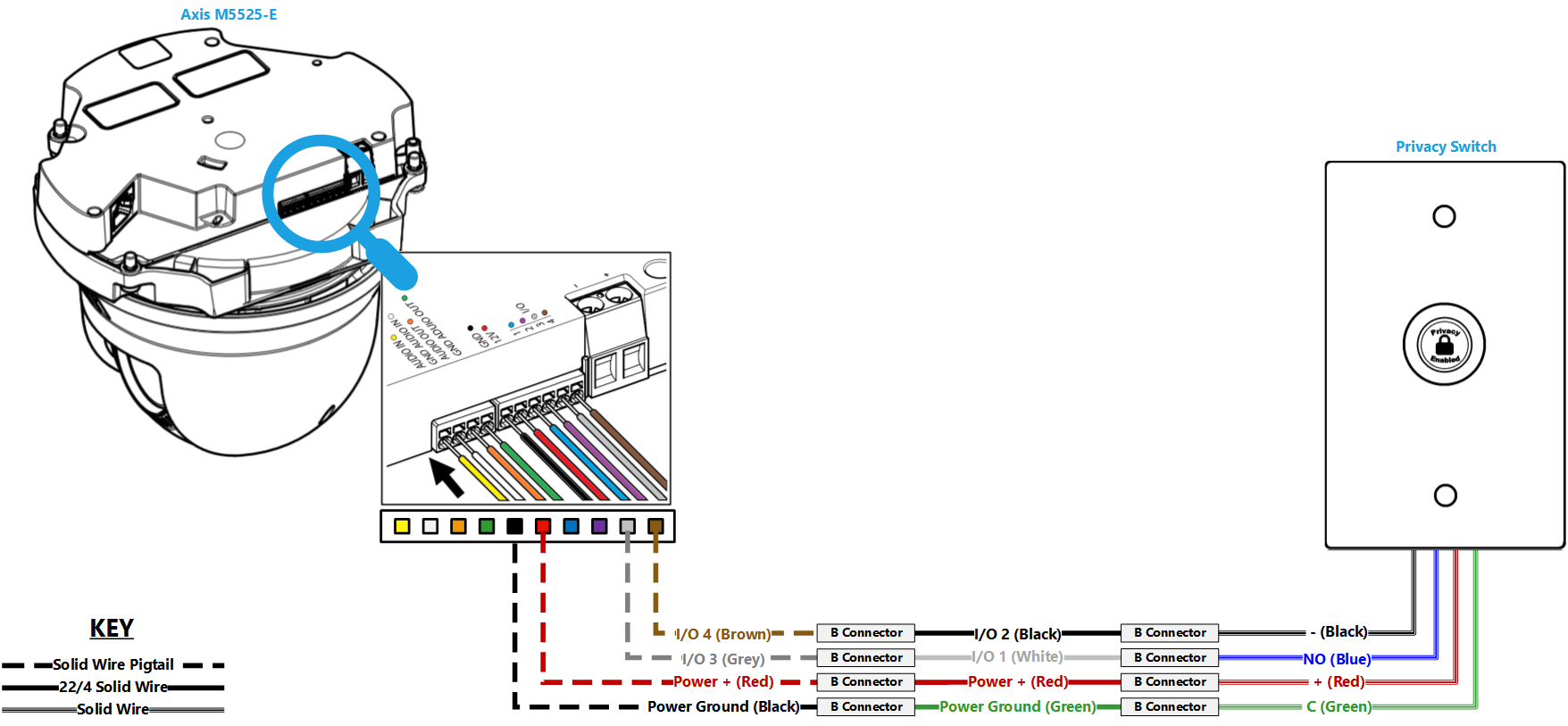
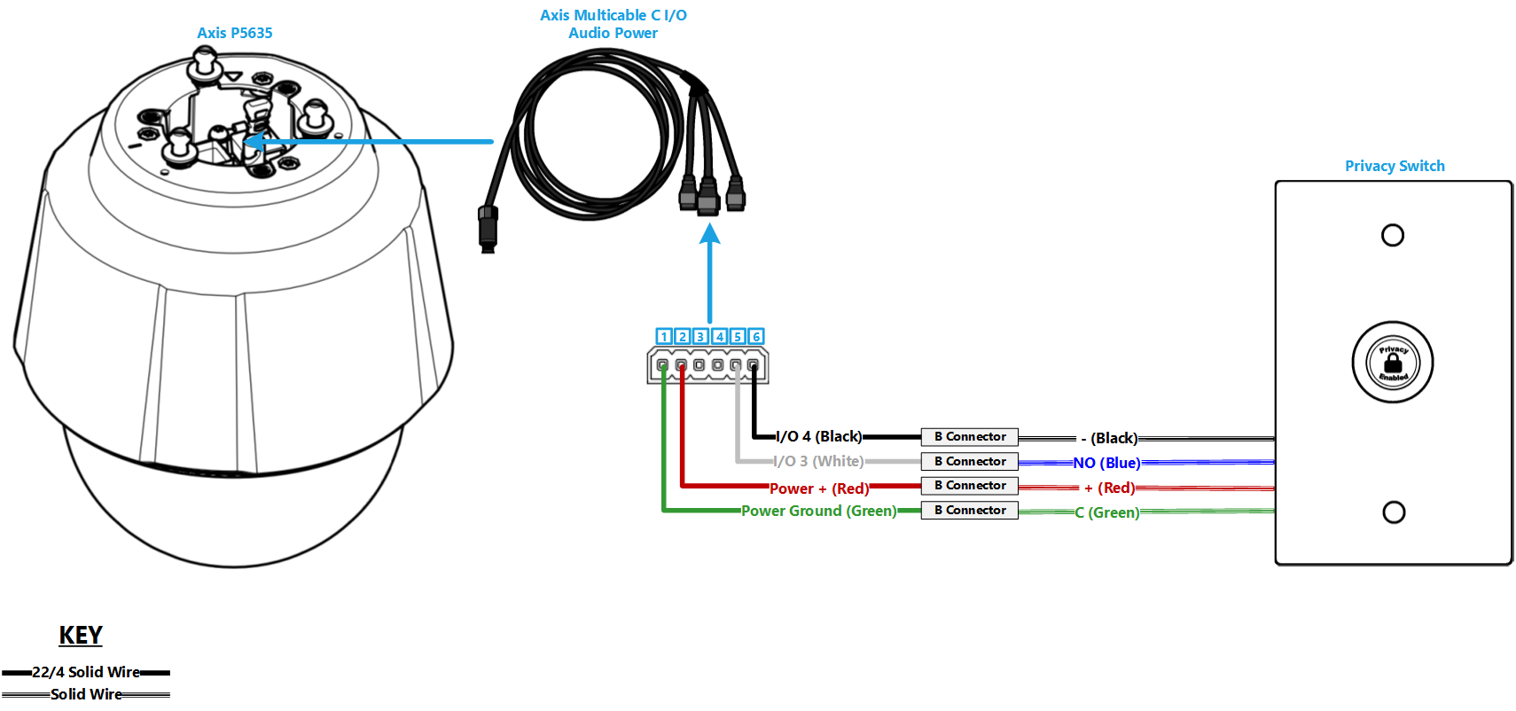
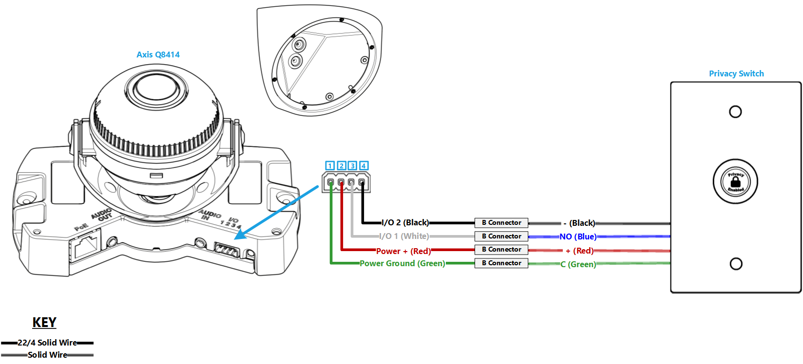
# Insert the wires into the IO connector on the camera according to the chart below. (For a camera with a 4-pin I/O phoenix connector, use pins 3 and 4 instead of 5 and 6.) | # Insert the wires into the IO connector on the camera according to the chart below. (For a camera with a 4-pin I/O phoenix connector, use pins 3 and 4 instead of 5 and 6.) | ||
| − | #: | + | #: {{img | file = Privacy3.jpg | width=375px}} |
#: Pin 1: Green | #: Pin 1: Green | ||
#: Pin 2: Red | #: Pin 2: Red | ||
| Line 76: | Line 74: | ||
#:: ''See the chart at the end of this section for a direct mapping between the switch and I/O connector'' | #:: ''See the chart at the end of this section for a direct mapping between the switch and I/O connector'' | ||
# Strip approximately 1/2 inch of insulation off each wire in the 22/4 on the switch side. | # Strip approximately 1/2 inch of insulation off each wire in the 22/4 on the switch side. | ||
| − | #: | + | #: {{img | file = Privacy4.jpg | width=375px}} |
# Attach the switch to the mud ring. | # Attach the switch to the mud ring. | ||
# Splice the wires to the switch according to the chart below. | # Splice the wires to the switch according to the chart below. | ||
| − | #: | + | #: {{img | file = PrivacyButton StartButton.png | width=375px}} |
* ''Connections should be made with B connectors'' | * ''Connections should be made with B connectors'' | ||
| Line 85: | Line 83: | ||
<br /> | <br /> | ||
'''Wiring Map''' | '''Wiring Map''' | ||
| − | + | <table> | |
| − | + | <tr> | |
| − | + | <th style="width:100px;">Privacy Switch</th> | |
| − | + | <th>Lead Color</th> | |
| − | + | <th>Phoenix Connector</th> | |
| − | + | </tr> | |
| − | + | <tr> | |
| − | + | <td>Switch</td> | |
| − | + | <td>Green</td> | |
| − | + | <td>Pin 1</td> | |
| − | + | </tr> | |
| − | + | <tr> | |
| − | + | <td>+</td> | |
| − | + | <td>Red</td> | |
| − | + | <td>Pin 2</td> | |
| − | + | </tr> | |
| − | + | <tr> | |
| − | + | <td>Switch</td> | |
| − | + | <td>Blue</td> | |
| − | + | <td>Pin 5</td> | |
| − | + | </tr> | |
| − | + | <tr> | |
| − | + | <td>-</td> | |
| − | + | <td>Black</td> | |
| − | + | <td>Pin 6</td> | |
| − | + | </tr> | |
| − | + | </table> | |
| − | + | }} | |
| − | |||
| − | |||
| − | |||
| − | |||
| − | |||
| − | |||
| − | |||
| − | |||
| − | |||
| − | |||
| − | |||
| − | |||
| − | |||
| − | |||
| − | |||
| − | |||
| − | |||
| − | |||
| − | |||
| − | |||
| − | |||
| − | |||
| − | |||
| − | |||
| − | |||
| − | |||
| − | |||
| − | |||
| − | |||
| − | |||
| − | |||
| − | |||
| − | |||
| − | |||
| − | |||
| − | |||
| − | |||
| − | |||
| − | |||
| − | |||
| − | |||
| − | |||
| − | |||
| − | |||
| − | |||
| − | |||
| − | |||
| − | |||
| − | |||
| − | |||
| − | |||
| − | |||
| − | |||
| − | |||
| − | |||
| − | |||
| − | |||
| − | |||
| − | |||
| − | |||
| − | |||
| − | |||
| − | |||
| − | |||
| − | |||
| − | |||
| − | |||
| − | |||
| − | |||
| − | |||
| − | |||
| − | |||
| − | |||
| − | |||
| − | |||
| − | |||
| − | |||
| − | |||
| − | |||
| − | |||
| − | |||
| − | |||
| − | |||
| − | |||
| − | |||
| − | |||
| − | |||
| − | |||
| − | |||
| − | |||
| − | |||
| − | |||
| − | |||
| − | |||
| − | |||
| − | |||
| − | |||
| − | |||
| − | |||
| − | |||
| − | |||
| − | |||
| − | + | {{Top of Page}} | |
| − | + | {{hr}} | |
| − | + | --> | |
| − | + | {{:Configuring a Privacy Switch}} | |
| − | + | }} | |
| − | |||
| − | |||
| − | |||
| − | |||
| − | |||
| − | |||
| − | |||
| − | |||
| − | |||
| − | |||
| − | |||
| − | |||
| − | |||
| − | |||
| − | + | [[Category:Accessories]] | |
| − | |||
| − | |||
| − | |||
| − | |||
| − | |||
| − | |||
| − | |||
| − | |||
| − | |||
| − | |||
| − | |||
| − | |||
| − | |||
| − | |||
Latest revision as of 10:32, 30 July 2025
Introduction
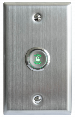
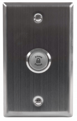
The VALT Privacy Button is a physical button that can be installed inside of a room that has cameras connected to VALT. This button allows a user to put a mask over the video and mute the audio, at the camera level. To enable and disable this privacy mode, a user must toggle the button.
 |
 |
Technical Specifications
| Technical Specifications | |
|---|---|
| Installation hole diameter: | 22MM |
| Head shape: | P-flat head |
| Contact type: | 1NO |
| Operation type: | Z-self-locking (Latching) |
| LED voltage: | 12V-DC12V, 24V-DC24V, custom: 5V-DC5V |
| Shell material: | S-stainless steel |
| Protection level: | Waterproof IP65 (IP68 customizable; button surface will not work if water is present), anti-collision IK10 |
| Resistive load: | AC-12:220V:2A DC-13:12V/24V:2A |
| Inductive load: | AC-12:110V/220V:0.3A DC-13:12V/24V:0.3A |
| Contact resistance: | <50mΩ |
| LED rated current: | <24V,<20mA; >24V,<10mA |
| LED life: | >50000h |
| Product certified: | CCC, CE, ROHS (customized), REACH (customized) |
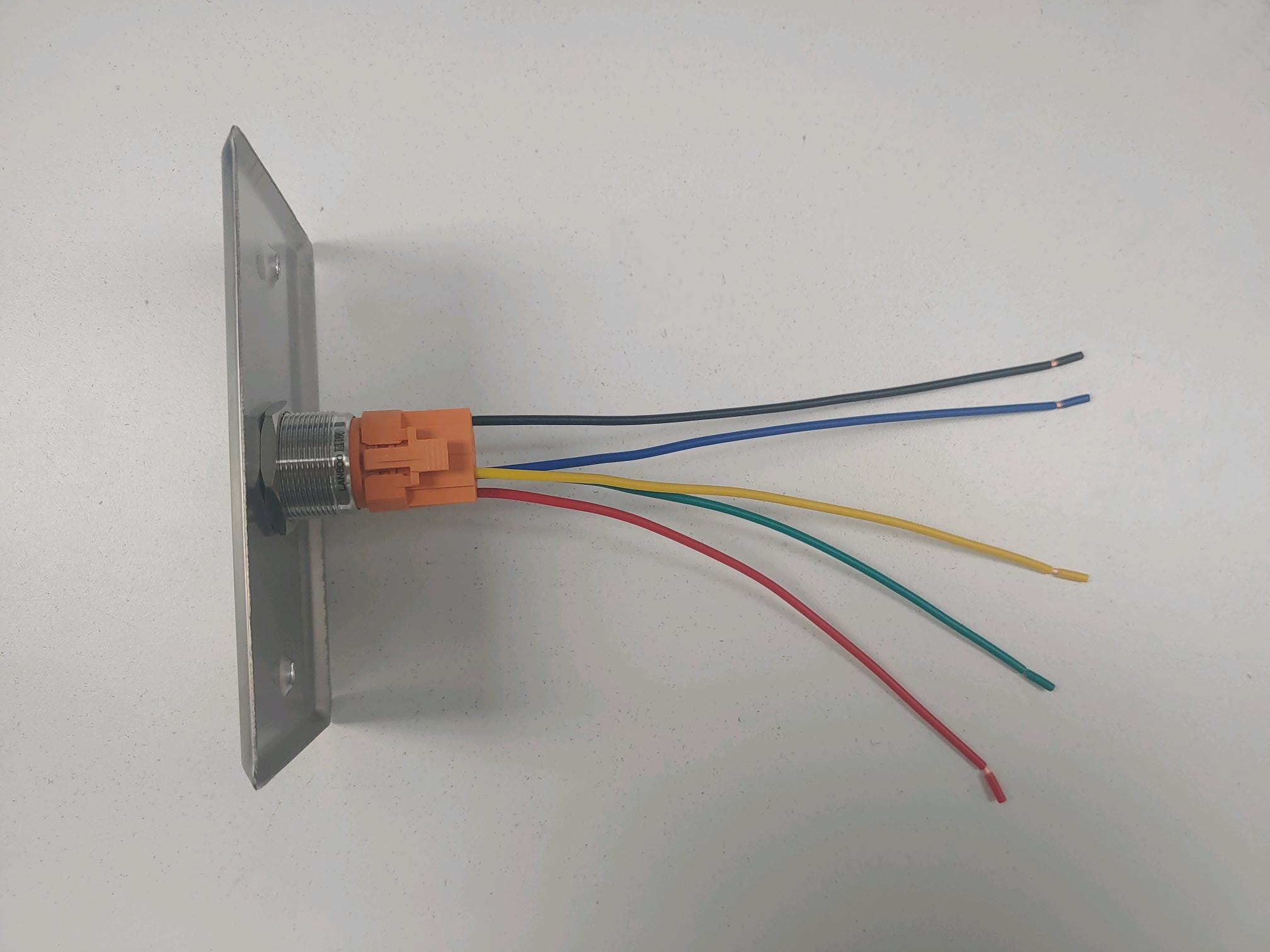
Physical Connections
Wiring
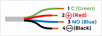
Between the cameras and the privacy button, there are two different cables. The first cable related to this is the one attached to the the physical button.
The physical button wires will look like this:
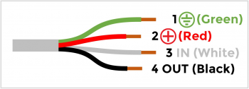
The second cable connection is the cable that will plug directly into the camera.
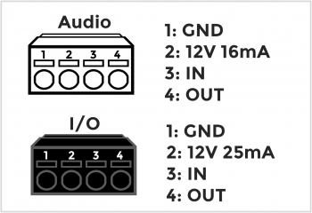
Axis IO Blocks
Of the supported cameras that IVS uses, many of the devices use I/O blocks to connect audio, power, and VALT accessories.
Compatible Cameras and Wire Diagrams
The privacy switch should be usable with any AXIS camera with at least one free input and one free output. The camera must be running firmware version 5.50 or higher.
Configuring a Privacy Switch
Prepare all Cameras
On each camera in the room:
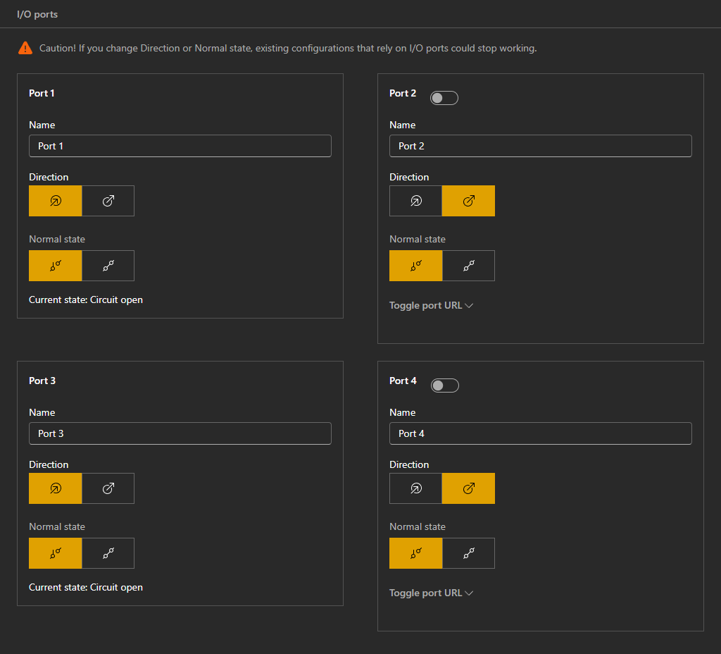
Set the I/O Ports
The Input/Output (I/O) ports will be wired to the Privacy Switch. These are used to determine which mode the camera should be in and outputs power to the Privacy Switch to light up the LED.
- Go to System → Accessories
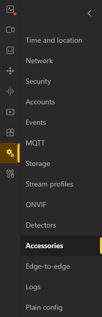 🖼️.
🖼️. - Ensure that Ports 1 & 3 are set as Input and 2 & 4 are set as Output.

| Port 1 | Input | Port 2 | Output | |
|---|---|---|---|---|
| Port 3 | Input | Port 4 | Output | |
Set the PTZ Presets
If there are any PTZ cameras in the room, you will need to set the preset positions on those cameras. These locations will help drive the camera to its Privacy Position and Home Position.
- Pan/Tilt/Zoom your camera to the desired angle.
- Go to PTZ → Preset Positions
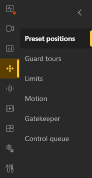 🖼️.
🖼️. - Select Preset Positions → Create preset position
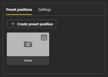 🖼️.
🖼️. - Home
- Set a typical angle that would capture the room normally.
- In the Name field enter Home.
- Privacy
- Typically, this involves having the PTZ face the wall.
- In the Name field enter Privacy.


Set the Privacy Mask
The Privacy Mask will be used to block the view
While your camera is in the Privacy Position:
- Video → Privacy Masks
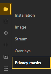 🖼️ → Hit the plus (+) button to add a Mask.
 - Have the mask cover the entire view.
- Name the mask Privacy.
- Make sure this is the first/only mask.

Add Recipients
The privacy switch is driven by custom rules/events created on the camera. These rules are sent to all cameras through Recipients.
Add Self
- Go to System → Events
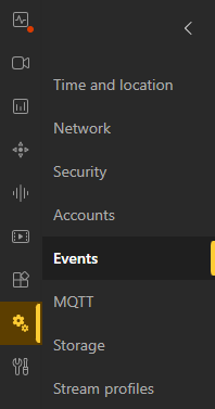 🖼️ → Recipients
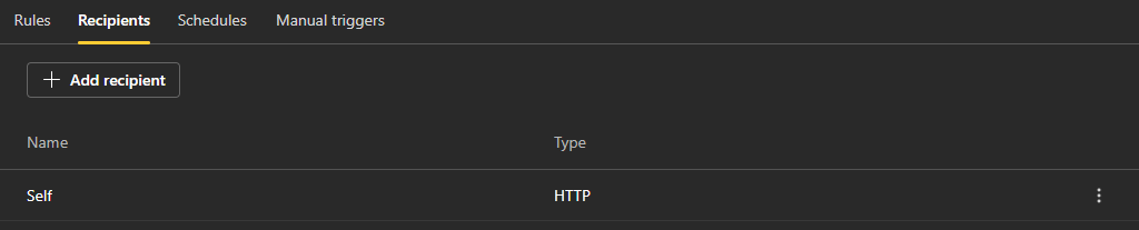 🖼️.
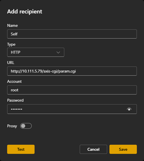
🖼️. - Select Add Recipient.
- In the Name field, enter Self as the name of the camera.
- In the Type
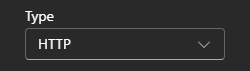 🖼️ field, select HTTP.
 - The URL
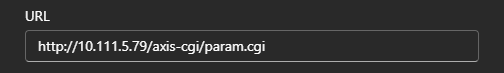 🖼️ of the recipient will be in the form:
 http://CAMERA_IP/axis-cgi/param.cgi


Add Remote Cameras
If there is more than one camera in thme setup, be sure to add additional recipients. This will allow you to create additional rules later to tell thme remote cameras what to do when privacy is enabled/disabled.
All Remote Recipients
Repeat the steops from Add Self, but change the Name to Remote.
Remote PTZ Recipients
For remote PTZ cameras, separate PTZ Control recipients need to be made alongside the standard recipient of the form:
http://CAMERA_IP/axis-cgi/com/ptz.cgi
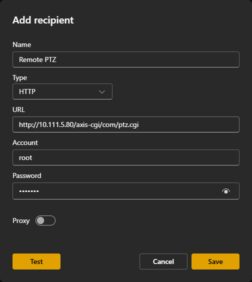
- Enter in the corresponding Username and Password for the recipient camera.
- Hit the Test button.
- If the camera responds that everything is okay, hit the Save button to save your recipient.
Add Privacy Event Rules
Privacy On
- Go to System → Events🖼️ → Rules
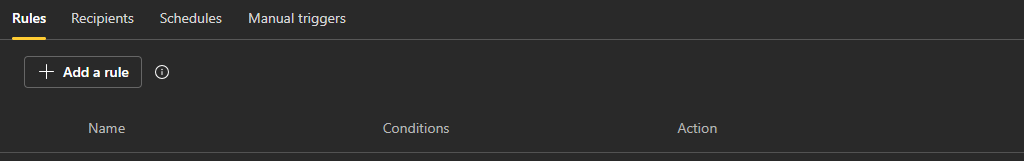 🖼️.
🖼️. - Select Add a rule.
- Set Name to Privacy On.
- Set Condition to Digital input is active or I/O → Digital input. (Firmware Dependent)
- In the Port section, select the port the privacy switch trigger is connected to (white wire).
- Set Action to Send notification through HTTP.
- Set the Recipient.
- The Query string suffix will be of the form
name=valuefor each parameter name and value, with an ampersand (&) between each name/value pair.

The suffix should be composed of the following pairs:
| Fixed & PTZ | |
|---|---|
| Name | Value |
| action | update |
| Image.I0.Overlay.MaskWindows.M0.Enabled | yes |
| AudioSource.A0.InputGain | mute |
| PTZ Only | |
| Name | Value |
| PTZ.Various.V1.PanEnabled | false |
| PTZ.Various.V1.TiltEnabled | false |
| PTZ.Various.V1.ZoomEnabled | false |
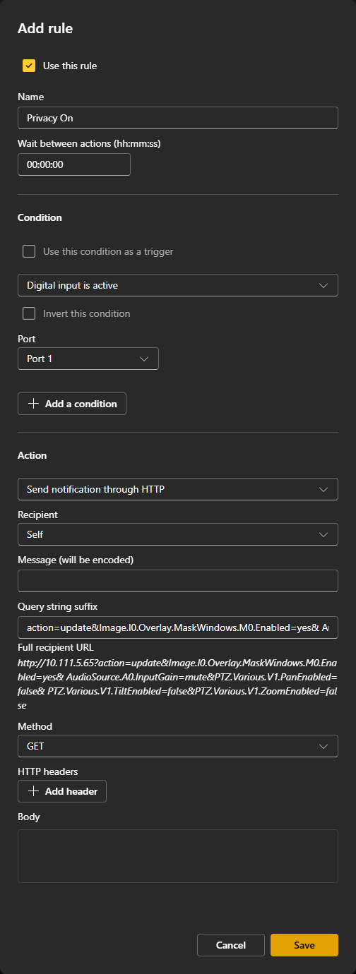
The completed suffix should be (ignore word wrapping):
action=update&Image.I0.Overlay.MaskWindows.M0.Enabled=yes&AudioSource.A0.InputGain=mute&PTZ.Various.V1.PanEnabled=false&PTZ.Various.V1.TiltEnabled=false&PTZ.Various.V1.ZoomEnabled=false
Privacy Off
- Go to System → Events🖼️ → Rules🖼️.
- Select Add a rule.
- Set Name to Privacy Off.
- Set Condition to Digital input is active or I/O → Digital input. (Firmware Dependent)
- Check the box Invert this condition.
- In the Port section, select the port the privacy switch trigger is connected to (white wire).
- Set Action to Send notification through HTTP.
- Set the Recipient.
- The Query string suffix will be of the form
name=valuefor each parameter name and value, with an ampersand (&) between each name/value pair.
The suffix should be composed of the following pairs:
| Fixed & PTZ | |
|---|---|
| Name | Value |
| action | update |
| Image.I0.Overlay.MaskWindows.M0.Enabled | no |
| AudioSource.A0.InputGain | 0 |
| PTZ Only | |
| Name | Value |
| PTZ.Various.V1.PanEnabled | true |
| PTZ.Various.V1.TiltEnabled | true |
| PTZ.Various.V1.ZoomEnabled | true |
| autofocus | on |
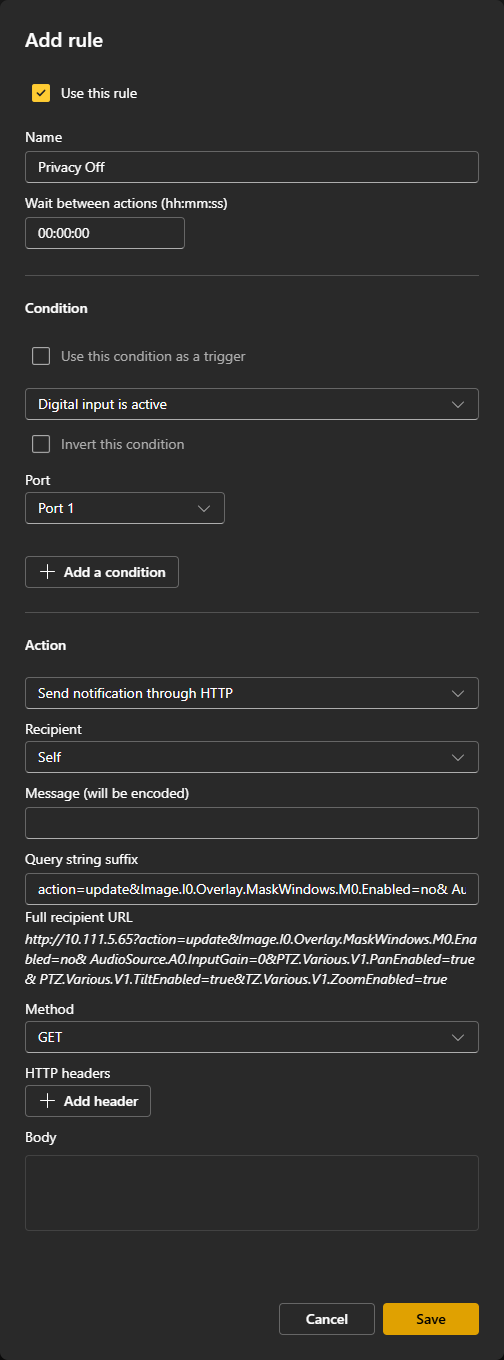
The completed suffix should be (ignore word wrapping):
action=update&Image.I0.Overlay.MaskWindows.M0.Enabled=no&AudioSource.A0.InputGain=0&PTZ.Various.V1.PanEnabled=true&PTZ.Various.V1.TiltEnabled=true&PTZ.Various.V1.ZoomEnabled=true
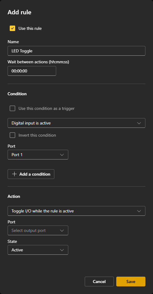
LED Toggle
On the Host Camera:
- Go to System → Events🖼️ → Rules🖼️.
- Select Add a rule.
- Set Name to LED Toggle.
- Set Condition to Digital input is active or I/O → Digital input. (Firmware Dependent)
- In the Port section, select the port the privacy switch trigger is connected to (white wire).
- Set Action to Toggle I/O while the rule is active.
- Set the Action Port to the port the privacy switch LED is connected to (black wire).
- Set the Action State to Active.
PTZ Rules
The following rules will be used to move the camera to a privacy location when privacy is enabled, and then move to a home location once privacy is disabled.
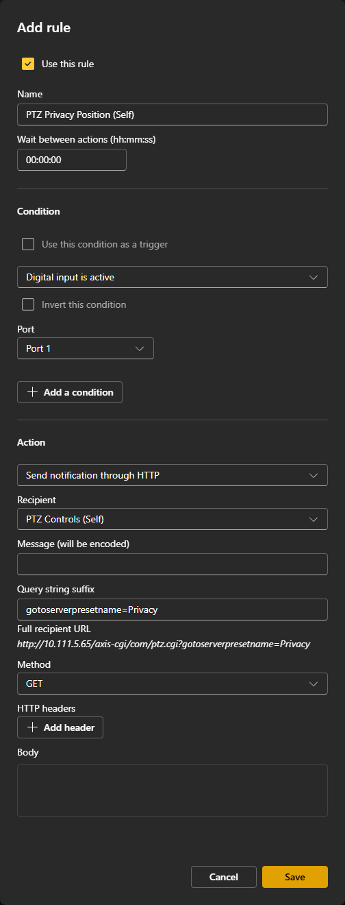
PTZ Privacy
- Go to System → Events🖼️ → Rules🖼️.
- Select Add a rule.
- Set Name to the camera name with PTZ Privacy Position.
- Set Condition to Digital input is active or I/O → Digital input. (Firmware Dependent)
- In the Port section, select the port the privacy switch trigger is connected to (white wire).
- Set Action to Send notification through HTTP.
- Set the Recipient to be the proper PTZ Controls Recipient.
- The Query string suffix should be:
gotoserverpresetname=Privacy
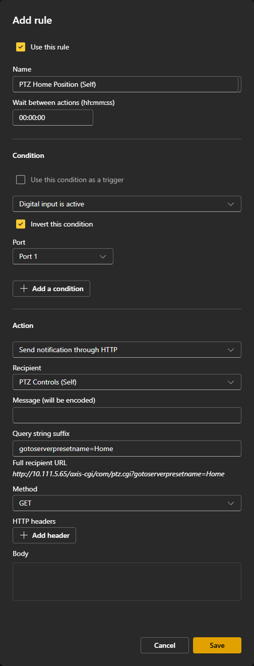
PTZ Home
- Go to System → Events🖼️ → Rules🖼️.
- Select Add a rule.
- Set Name to the camera name with PTZ Home Position.
- Set Condition to Digital input is active or I/O → Digital input. (Firmware Dependent)
- Check the box Invert this condition.
- In the Port section, select the port the privacy switch trigger is connected to (white wire).
- Set Action to Send notification through HTTP.
- Set the Recipient to be the proper PTZ Controls Recipient.
- The Query string suffix should be:
gotoserverpresetname=Home