Difference between revisions of "RDL ST-VOX1"
IVSWikiBlue (talk | contribs) (→Data Sheet) |
IVSWikiBlue (talk | contribs) (→Data Sheet) |
||
| (One intermediate revision by the same user not shown) | |||
| Line 22: | Line 22: | ||
Adjust sensitivity and delay as needed; 25 turns sets to max of 5 seconds. | Adjust sensitivity and delay as needed; 25 turns sets to max of 5 seconds. | ||
| + | |||
| + | [[File:vox.jpg|500px|thumb|right||link=]] | ||
== Data Sheet == | == Data Sheet == | ||
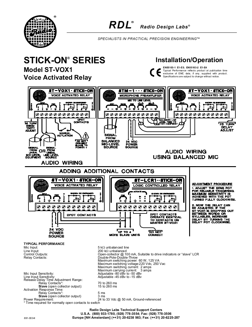
| − | + | {{img | file = ST-VOX1.png}} | |
Latest revision as of 15:35, 9 May 2022
How to Wire
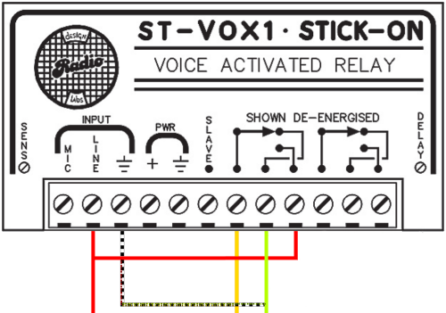
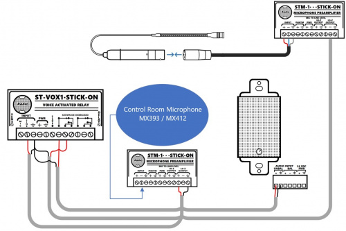
Set up microphone and STM-1 as usual, but send HI-Z Audio out to the VOX input line.
Connect audio line to positive on VOX, leave ground out for future b-connecting or terminal block connection.
Insert jumper wire connecting the audio input line to the final dot on the first collection of dots and lines, the first relay circuit. This allows the observation microphone in this case to be used as the alternative source for when the VOX fires off while it is being used.
Connect power, no jumpers and in it’s own dedicated ground slot.
Skip the slave terminal, unless you have another relay to connect to.
On the first dot, the first slot of the relay, insert your output’s audio line, leaving the ground for the line out for, once again, future grounding.
You’ll repeat the same process for the next slot in the relay, except with your second audio source.
Connect all grounds with your preferred method, and connect to ground next to input
Adjust sensitivity and delay as needed; 25 turns sets to max of 5 seconds.


