Difference between revisions of "M5525 Shure MX202i W/P"
IVSWikiBlue (talk | contribs) (→Required Parts And Tools) |
IVSWikiBlue (talk | contribs) (→Required Parts And Tools) |
||
| Line 9: | Line 9: | ||
* Wire Stripper | * Wire Stripper | ||
*:[[File:Wire_Stripper_and_Starbit_Driver.JPG|60x80px]] | *:[[File:Wire_Stripper_and_Starbit_Driver.JPG|60x80px]] | ||
| − | + | ||
| − | |||
* Phillips head drill bit or Phillips head screwdriver | * Phillips head drill bit or Phillips head screwdriver | ||
* Small Flat head screwdriver | * Small Flat head screwdriver | ||
Revision as of 11:36, 22 March 2018
Required Parts And Tools
- Stud Finder
Connecting the STM-
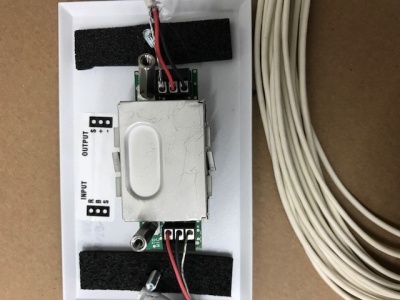
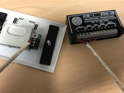
- Connect MX202WP/C Microphone to the input of the provided wall plate. Connect 22/2 cable to the audio output of that wall plate. VERY IMPORTANT to make the connections AS diagrammed (see below)
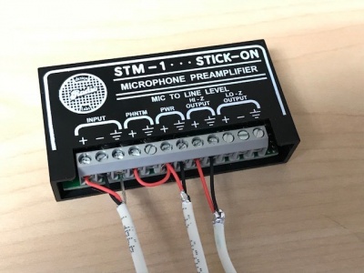
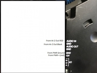
- Connect the output 22/2 cable to the input of the STM-1 (Red to +, Black to -, bare wire to ground). Connect 22/2 wire to the power of the STM-1 (red to + and black to -). Connect the other end of that cable to the IO Connectors on the M5525 labeled 12V and GND (Red to 12V and BLK to GND). Using 22/2 cable, connect the red and black to the HI-Z output (red to + black to -). Connect the other end of that cable to the to the IO Connectors on the M5525 labled Audio IN and GND (red to Audio IN and Black to GND)
(NOTE; If there are 2 cameras in the room, duplitcate step 9.1.3 using a long enough cable to get to the 2nd camera. If there are 2 Shure MX202i Microphones, duplicate step 9.1.4.)


