Difference between revisions of "Start/Stop Button"
IVSWikiBlue (talk | contribs) (→IO Configuration) |
IVSWikiBlue (talk | contribs) (→IO Configuration) |
||
| Line 2: | Line 2: | ||
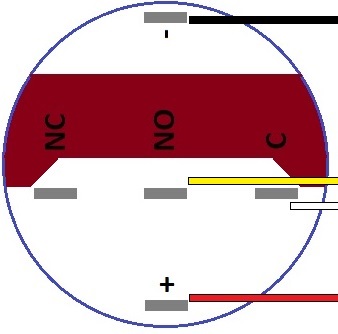
First wire the button to the desired camera's IO phoenix connector. If you are using our buttons, the wires should be connected to the back of the button as shown in the diagram below. | First wire the button to the desired camera's IO phoenix connector. If you are using our buttons, the wires should be connected to the back of the button as shown in the diagram below. | ||
| − | [[File: | + | [[File:BTNDiag.jpg]] |
{|style="text-align:center;" | {|style="text-align:center;" | ||
Revision as of 10:39, 23 August 2016
IO Configuration
First wire the button to the desired camera's IO phoenix connector. If you are using our buttons, the wires should be connected to the back of the button as shown in the diagram below.
| Button | Phoenix Connector |
|---|---|
| NC | Pin 1 |
| + | Pin 2 |
| C | Pin 3 |
| - | Pin 4 |
We recommend wiring the buttons using CAT6 as shown below:
Next you will need to go into the admin section under the wired room within our software and define what camera has the button IO hooked up as shown below.
Lastly you will need to add the I/O Records right to any user group you want to be able to review recordings crated by the push button as shown below.


