Difference between revisions of "Template:F41 VerifactA"
IVSWikiBlue (talk | contribs) (Created page with "==Connecting the Microphone== #Mark center of the ceiling tile the Verifact A will be mounted on. #Using a hole saw, drill a hole at center of the ceiling tile. Feed one end o...") |
IVSWikiBlue (talk | contribs) (→Connecting the Microphone) |
||
| Line 3: | Line 3: | ||
#Using a hole saw, drill a hole at center of the ceiling tile. Feed one end of the the 22/2 cables through the hole. | #Using a hole saw, drill a hole at center of the ceiling tile. Feed one end of the the 22/2 cables through the hole. | ||
#:''Note:'' Ensure that the hole will be covered by the microphone | #:''Note:'' Ensure that the hole will be covered by the microphone | ||
| − | #: [[File:VerifactACutHole.jpg|link=https://ipivs.com/wiki/images/c/ca/VerifactACutHole.jpg]] | + | #: [[File:VerifactACutHole.jpg|link=https://ipivs.com/wiki/images/c/ca/VerifactACutHole.jpg|300px]] |
#Strip the jacket off the 22/2, revealing the red, black, and common (bare wire) on both sides of the cable. | #Strip the jacket off the 22/2, revealing the red, black, and common (bare wire) on both sides of the cable. | ||
#Remove the string and plastic casings covering the red and black cables. | #Remove the string and plastic casings covering the red and black cables. | ||
Revision as of 09:38, 27 August 2020
Connecting the Microphone
- Mark center of the ceiling tile the Verifact A will be mounted on.
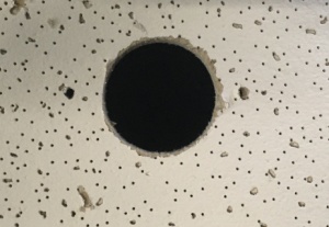
- Using a hole saw, drill a hole at center of the ceiling tile. Feed one end of the the 22/2 cables through the hole.
- Strip the jacket off the 22/2, revealing the red, black, and common (bare wire) on both sides of the cable.
- Remove the string and plastic casings covering the red and black cables.
- Strip the red and black jackets off the wire exposing the copper. Cut copper evenly on both ends. Remove ground.
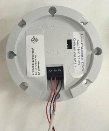
- At the Verifact A, connect the power cable to ports A and C. Connect the audio cable to ports B and C.
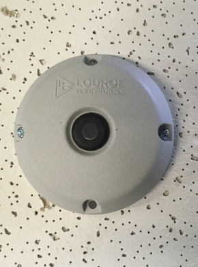
- Using toggle bolts, secure the microphone.
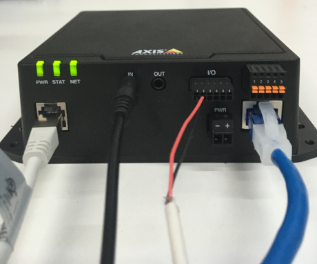
- Connect the other ends of the 22/2 cable to the terminals on F41.


