Installing an Axis P5414/P5415 with a Shure MX202i Microphone
Revision as of 13:58, 3 January 2017 by IVSWikiBlue (talk | contribs)
Required Parts And Tools
- Axis P5415 or P5415

- RDL STM-1

- XLR-F Pigtail

- Shure MX202i Microphone

- Starbit Security Driver
- Wire Stripper

- Anchors and Screws

- 1/2" paddle bit
- 1 blank single gang wall plate

- Toggle Bolts (If mounting to drop ceiling tile)

- Drill bit and drill

- Phillips head drill bit or Phillips head screwdriver
- Small Flat head screwdriver

- Hole Saw

- B Connectors

- Stud Finder
- Cat5/6 Patch Cable (7ft-15ft recommended)

- 22/2 Gauge Wire

- Fish Tape or Glow Rod


Installation Instructions
- Locate the network drop that is ran back to the HIGH POE switch. (If the switch does not have HIGH POE, you will need to insert a HIGH POE injector back at the network closet).
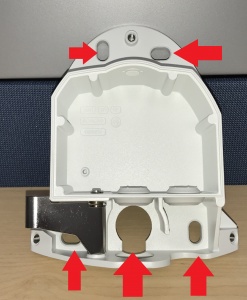
- Remove the P5414/P5415 camera from its base with the starbit security driver. Place the base of the camera on the wall where you’d like to mount. Using a stud finder, ensure there aren’t any studs any behind the camera base. Using a marker or pen, mark the 4 areas on the wall where the screws would be and also mark the opening where the any cabling would come through (Areas labeled on picture).
- Connect the network drop into the RJ-45 (f) on the IFPX that reads “Power+Data In” When connected you should see activity on the link lights. If no link lights, ensure that POE is enabled on your POE switch and that the network drop is plugged in.
- Mount your Axis P3364 or P3365 to either the wall below (using anchors and screws), or the drop ceiling tile (using the toggle bolts).
- Using the CAT5/6 patch cable, connect the camera to the RJ-45 (f) on the IFPX labeled “Power+Data Out.” When connected, you should see the “Net” “Status” and “Power” LEDs light up on the camera. After approximately 1 minute, all 3 should be green. If not, check connections.
- Take the 3.5mm Male to Male audio cable and connect it from the 3.5mm jack labeled “Audio Out” on the IFPX into the pink “AUDIO IN” on the P3364 or P3365 camera. (See Picture)
- Strip the jacket off the 22/2, revealing the red, black, and common (bare wire) on both sides of the cable. Remove the string and plastic casings covering the red and black cables. Strip the red and black jackets off the wire exposing the copper. Cut copper evenly on both ends (See picture)
- Drill a hole into the piece of ceiling tile that you will be mounting the Louroe Verifact-A. Feed one end of the the 22/2 audio cable through the hole. Connect the audio cable to the Verifact-A phoenix terminal as follows; Red to A, Black to B, Common (bare wire) to C (See Picture)
- Connect the other end of your 22/2 cable to the terminal on the IFPX labeled “MIC/SPEAKER A B C SP” The connections will be as follows; Red to A, Black to B, Common (bare wire) to C (See Picture)
- Place the dome over on the camera. Using the star bit security driver, tighten the dome cover in place.


