M5525 Shure MX202i
Revision as of 16:43, 18 February 2019 by IVSWikiBlue (talk | contribs)
Contents
Required Parts And Tools
- Axis M5525
- AXIS T94P01L Recessed Mount
- RDL STM-1
- XLR-F Pigtail
- Shure MX202i Microphone
- Starbit Security Driver
- Wire Stripper
- 1/2" paddle bit
- 1 blank single gang wall plate
- Toggle Bolts (If mounting to drop ceiling tile)
- Drill bit and drill
- Phillips head drill bit or Phillips head screwdriver
- Small Flat head screwdriver
- 22/2 Gauge Wire
- Razor
- B-Connectors
- Drywall Saw
- Wind Screen (Inside MX202i Box)
- Rubber Stopper (Inside MX202i Box)
- 4 pin XLR-M to XLR-M Adapter (Inside MX202i Box)
Installation Instructions
If using a recessed mount.
- Locate the network drop that is ran back to the POE switch. (If the switch does not have POE, you will need to insert a POE injector back at the network closet.)
- Using the instructions included in the Axis T94P01L box, use the razor to cut a hole into the drop ceiling tile and assemble the holding bracket for the camera. Mount bracket to drop ceiling.
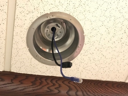
- Remove the dome from the M5525. The 22/12 pigtail and network cable should already be pre-docked in the camera. If not, you'll have to open the M5525, run the network drop through the mounting bracket and plug it in. (If the camera has both the pigtail and the network cable, simply run them both through the bracket into the ceiling.)
- Use the screws included with the mounting bracket to affix the M5525 to the recessed mount. Reattach the dome. Then affix the mounting disc to cover the ceiling tile.
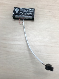
- Cut 2 lengths of 22/2 cable long enough to go from the M5525 pigtail to the STM-1. One is for audio; the other is to power the STM-1.
- Strip the jacket and wire shielding about 1/2" to expose the wires. Connect the cable for power (Red to red, Black to black). Connect the cable for audio (red to yellow; black to white).
If mounting flush to a ceiling tile.
- Locate the network drop that is ran back to the POE switch. (If the switch does not have POE, you will need to insert a POE injector back at the network closet.)
- Remove the dome from the M5525.
- Make marks on our ceiling tile where our toggle bolts will go, and a place where our cables will be run.
- Carefully use a blade to cut a hole in the tile to run cables.
The 22/12 pigtail and network cable should already be pre-docked in the camera. If not, you'll have to open the 5525, run the network drop through the ceiling tile and plug it in. (If the camera has both the pigtail and the network cable, simply run them both through the tile.)
- Use the toggle bolts to secure the camera to the ceiling tile. Reattach the camera dome.
- Cut 2 lengths of 22/2 cable long enough to go from the M5525 pigtail to the STM-1. One is for audio; the other is to power the STM-1.
- Strip the jacket and wire shielding about 1/2" to expose the wires. Connect the cable for power (Red to red, Black to black). Connect the cable for audio (red to yellow; black to white).
Connecting the STM-1
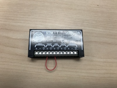
- Connect one end of the 1 inch 22/2 cable to the +PWR terminal and connect the other end into the +PHNTM terminal.
- Connect the other end of the 22/2 we ran for power to the PWR terminals (Red to +, Black to the other terminal) of the STM-1.
- Connect the cable we ran for audio to the HI-Z OUTPUT terminals (Red to +, Black to ground) of the STM-1.
- We will need another length of 22/2 cable intended for your microphone; connect it to the input terminals of the STM-1 (Red to +, Black to -, ground to the ground terminal). Using the Velcro that comes with the STM-1, attach the STM-1 to the wall above drop ceiling hidden from sight.
(NOTE; If there are 2 cameras in the room, duplicate these steps to get to the 2nd camera. LO-Z output can feed 2 cameras, but no more.
Connecting and Mounting the Microphone
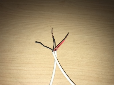
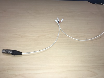
- Strip the jacket of the XLR pigtail revealing the red, black and common (silver) cables inside. Strip away a portion of the red and black cables inside the pigtail, revealing the copper wire inside. (This is typically already done before shipment from the office.) At the end of the 22/2 cable (connected to the STM-1 input), twist the wires together with the pigtail (red to red, black to black, common to common). Secure these with B-Connectors (See Pictures). Repeat this process if necessary for 2 microphones.
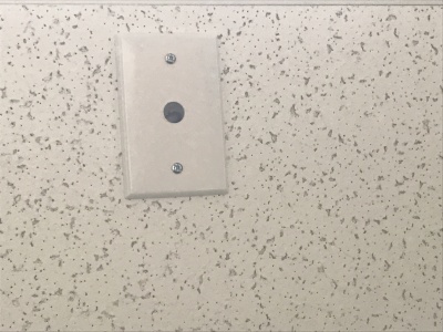
- Drill a hole into the center of the single gang plate using the ½” paddle bit, and a hole into the desired location for the microphone on your drop ceiling tile with a 1" paddle bit. Then secure this single gang plate to the desired location of the microphone on your drop ceiling tile using a pair of toggle bolts.
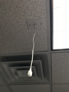
- Run your MX202i through the ½” hole in the ceiling tile and single gang plate. Connect the 4 Pin XLR-F end of the MX202i to the 4 pin XLR-M adapter. Next, connect the XLR-F (that is ran back to the STM-1) to the XLR-M of the adapter. Use the rubber stopper to plug the ½” hole in the single gang plate.
- Lastly, adjust the length of the cable of the microphone to your desired length, hiding the remainder in the ceiling near the STM-1. Attach the windscreen to the MX202i.


