Installing an Axis F41 and Axis F1025 sensor unit with Tesira Forte
Revision as of 12:16, 23 April 2020 by IVSWikiBlue (talk | contribs)
Contents
Required Parts And Tools
- Axis F41 Main Unit
- Axis F1025
- Axis F8001
- 3.5mm (Male to Male) Audio Cable
- Biamp Tesira Forte unit
- Biamp ceiling microphone
- S2 TT10 Torx security bit
- Wire Stripper
- Wall Dogs (if mounting to concrete) (3/16")
- Screws and Anchors (3/16")
- Toggle Bolts (If mounting to drop ceiling tile) (3/16")
- Drill bit and drill
- Phillips head drill bit or Phillips head screwdriver
- Small Flat head screwdriver (#3)
- Cat5/6 Patch Cable (7ft-15ft recommended)
- Shielded Stranded 22/2 + ground Wire
- 1 Mud ring if mounting to drywall, Datacom box if mounting to hard surface (ex. Cinderblock)
- Drywall Saw
- 1 blank single gang wall plate with 1/4" cut hole
Installation Instructions
Mounting the Processing Unit
- Locate the network drop above the ceiling. It should be terminated with a male Ethernet end (service loop) or a biscuit jack. This line will have been ran back to the POE switch.
- Note: If the switch does not have POE, a POE injector will need to be installed at the network closet.
- Using the T10 bit, remove the rubber feet from the bottom of the Axis F41 Main Unit, and replace it with the Axis F8001. This will allow the F41 to be mounted to drywall above the drop ceiling.
- Find the a suitable mounting location for the F41. Using a pencil, mark the location the four anchors will be mounted
- Using a drill and drill bit, drill the mounting locations
- Insert the four anchors and screws (or wall dogs), and mount the F41 into the drywall above the drop ceiling.
- Note: if there is no drop ceiling make other arrangements for mounting.
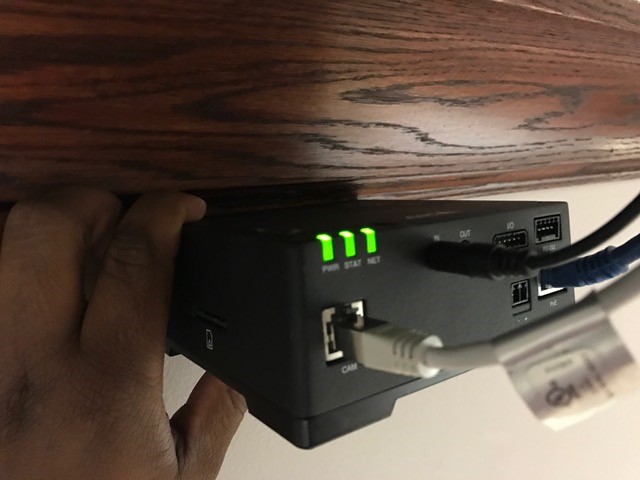
- Connect the network drop to the Axis F41 Main Unit. When connected, the NET, STATUS, and POWER LEDs will show green on the unit. After approximately one minute, all three indicators should be green.
Mounting the Camera
- Determine the proper mounting location for the Axis 1025
- Cut a hole into the drywall, large enough to fit the mud ring into it securely. (If mounting on a hard surface, attach Datacom box to the wall).
- Run the attached RJ-11 cable behind the drywall to the input labeled CAM on the Axis F41 Main Unit.
- Mount Axis F1025 to single gang wall plate, aligning the camera with the center cut hole. Once established, secure the faceplate to the mud ring (if not already secured).

Connecting the Microphone and Tesira
Wiring Diagram
