Installing an Axis M5525 with a Tesira Forte DSP
Contents
Required Parts And Tools
- Axis M5525
- AXIS T94P01L Recessed Mount
- Louroe Verifact D
- S2 TT20 Torx security bit
- Wire Stripper
- 1/2" paddle bit
- 1 blank single gang wall plate
- Wall Dogs (if mounting to concrete) (3/16")
- Screws and Anchors (3/16")
- Toggle Bolts (If mounting to drop ceiling tile, mic mount) (3/16")
- Drill bit and drill
- Phillips head drill bit or Phillips head screwdriver
- Small Flat head screwdriver (#3)
- Shielded Stranded 22/2 + ground Wire
- Razor / box cutter
- B-Connectors
- Drywall Saw
Installation Instructions
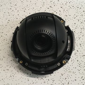
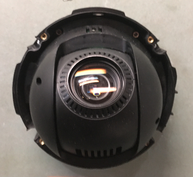
Disassemble Camera
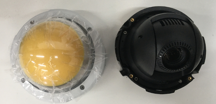
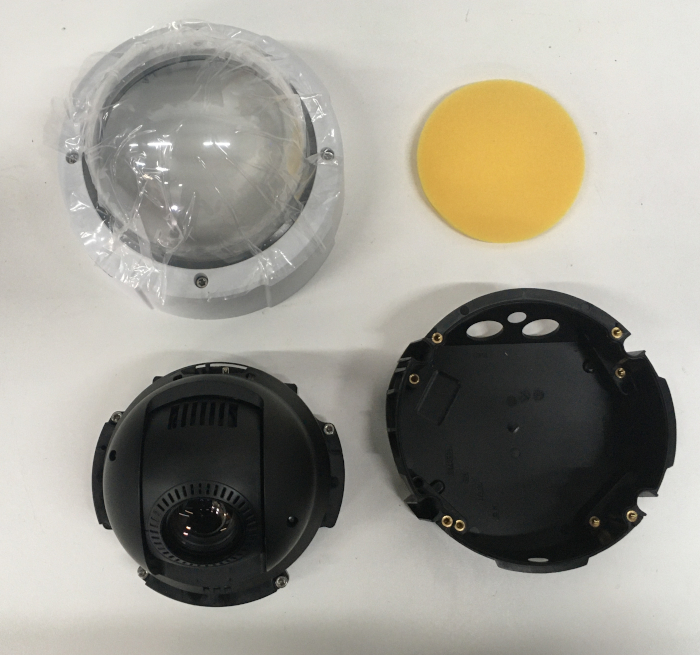
- Using the T20 bit , remove the dome from the M5525
- Remove the yellow packing foam.
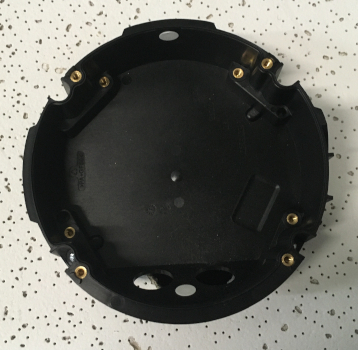
- Using the T20 bit, remove the camera from the mounting plate
Recessed Mount instructions
- Locate the network drop above the ceiling either being a male Ethernet end (service loop) or a biscuit jack. This will have been ran back to the POE switch.
- Note: If the switch does not have POE, a POE injector will need to be installed at the network closet.
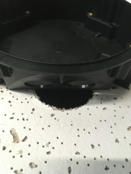
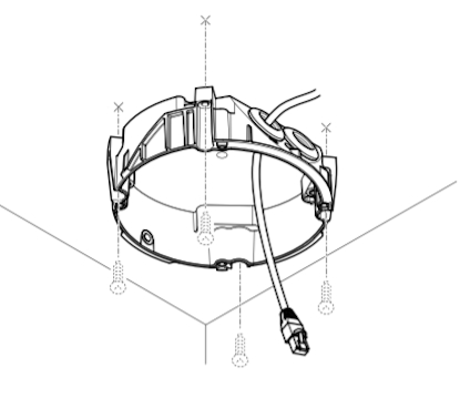
- Using the instructions included in the Axis T94P01L box, use the razor to cut a hole into the drop ceiling tile, and assemble the holding bracket for the camera.
- Mount bracket to drop ceiling.
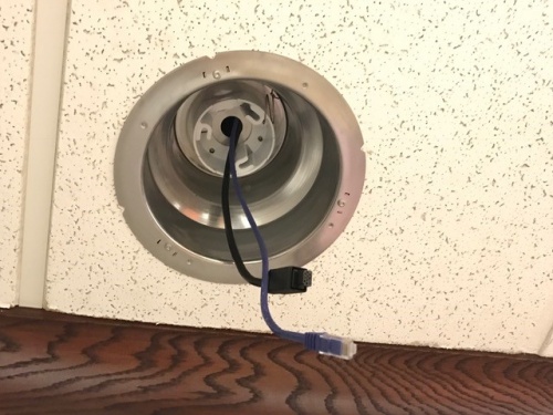
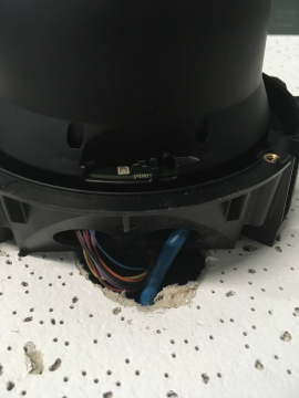
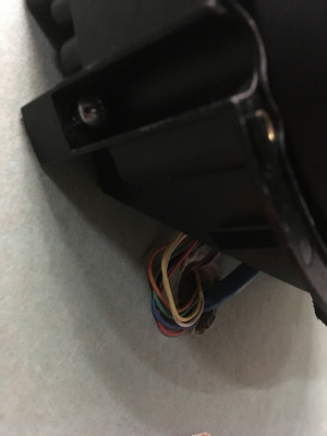
- Note: The 22/12 pigtail and network cable should already be pre-docked in the camera. If not, you'll have to open the M5525, run the cat 5 cable and pigtail through the mounting bracket and plug it in. (If the camera has both the pigtail and the network cable, simply run them through the bracket above the ceiling.)
- Use the screws included with the mounting bracket to affix the M5525 to the recessed mount.
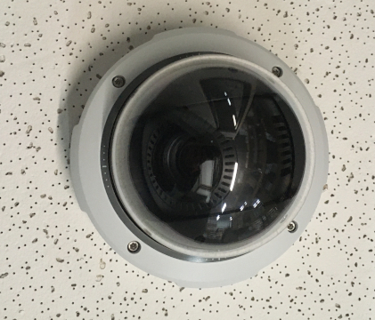
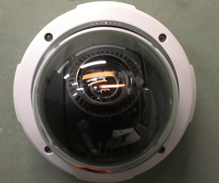
- Reattach the dome. Then affix the mounting disc to cover the ceiling tile.
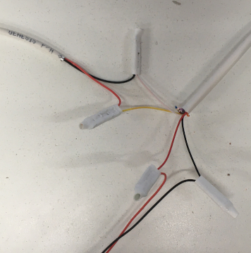
- Cut 2 lengths of 22/2 cable long enough to go from the M5525 pigtail to the Verifact A. One is for audio; the other is to power the microphone.
- Strip the jacket and wire shielding about 1/2" to expose the wires.
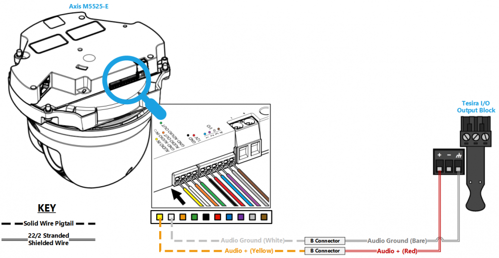
- Connect the cable for power to the pigtail with B-connectors (Red to red, Black to black). Connect the cable for audio (red to yellow; black to white).
Drop Ceiling Mounting Instructions
- Locate the network drop above the ceiling either being a male Ethernet end (service loop) or a biscuit jack.
- Note: This will have been ran back to the POE switch. If the switch does not have POE, a POE injector will need to be installed at the network closet.
- Make marks on the ceiling tile where the toggle bolts will go, and a place from where the cables will be run.
- Carefully use a blade to cut a hole in the tile to run cables.
- Use the toggle bolts to secure the mounting plate to the ceiling tile.
- Using the T20 bit, attach the camera to the mounting plate and run cables through ceiling tile
- Reattach the camera dome.
Drywall / Hard Ceiling Mounting Instructions
- Locate the network drop above the ceiling either being a male Ethernet end (service loop) or a biscuit jack.
- Note: This will have been ran back to the POE switch. If the switch does not have POE, a POE injector will need to be installed at the network closet.
- Using a stud finder, scan the mount location to ensure the camera is not mounted on a stud.
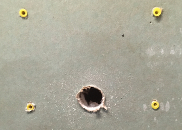
- Using a pencil, mark the four holes for the mount plate.
- Using a 3/16" drill bit, drill the marked locations
- Install anchors and attach the mount plate using screws and washers.
- Using a hole saw or paddle bit, cut a hole where cabling will pass through
- Using glow rods or fish tape, fish the network drop or patch cable in addition to the two sections of 22/2 audio cable through the drywall.
- Using the appropriate screws, attach the mounting plate
- Using the T20 bit, attach the camera to the mount plate
- Using the T20 bit, reattach the camera dome
Connecting Wiring
- Cut 2 lengths of 22/2 cable long enough to go from the M5525 pigtail to the microphone. One will be for audio. One will be for power
- Note: The 22/12 pigtail and network cable should already be pre-docked in the camera. If not, open the M5525, run the cat 5 cable and pigtail through the mounting bracket and plug it in (If the camera has both the pigtail and the network cable, simply run them both through the tile.).
- Strip the jacket and wire shielding about 1/2" to expose the wires.
- Connect the cable for power (Red to red, Black to black).
- Connect the cable for audio (red to yellow; black to white).
