Template:5655 Installation Instructions
Revision as of 14:53, 26 August 2020 by IVSWikiBlue (talk | contribs) (Created page with "==Installation Instructions== ===Mounting the Camera=== #Locate the network drop above the ceiling either being a male Ethernet end (service loop) or a biscuit jack. This wil...")
Installation Instructions
Mounting the Camera
- Locate the network drop above the ceiling either being a male Ethernet end (service loop) or a biscuit jack. This will have been ran back to the POE switch.
- Note: If the switch does not have POE, a POE injector will need to be installed at the network closet.
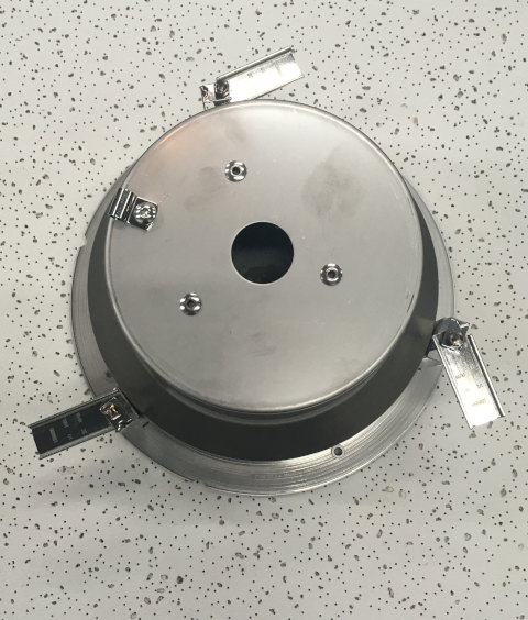
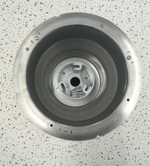
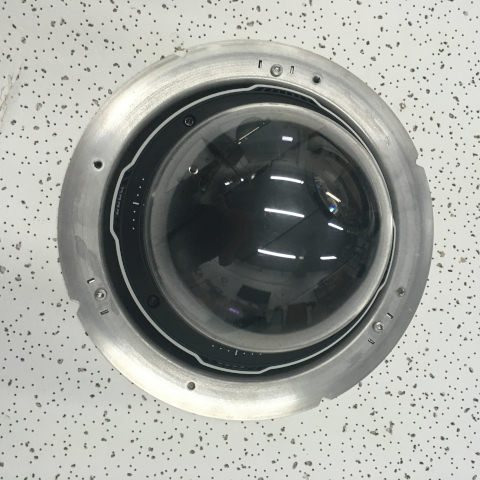
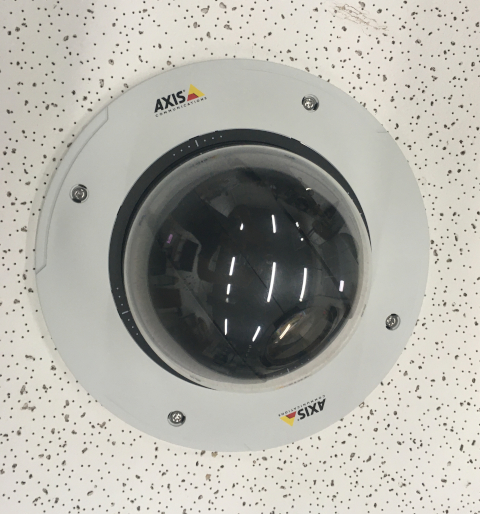
- Remove Axis T94A02L kit from packaging. This will include the mounting bracket and the camera dome ring.
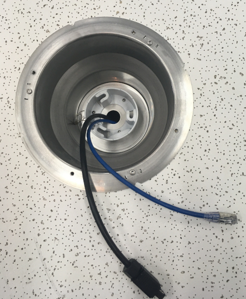
- Determine the location where the 5655 will be mounted and remove the ceiling tile
- Measuring the ceiling mount bracket, note that there is a slight lip to the camera mount
- Find center of the ceiling tile and using a pencil, draw a circle approximately nine inches in diameter
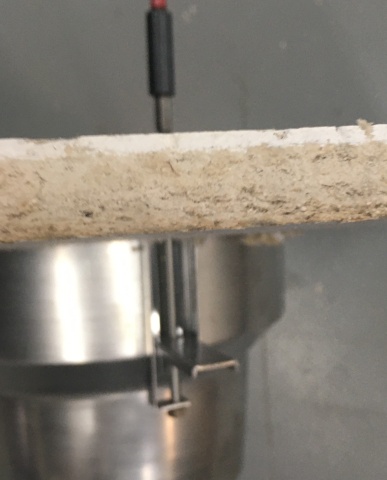
- Using a drywall saw, cut out the section of ceiling tile where the mount will be inserted
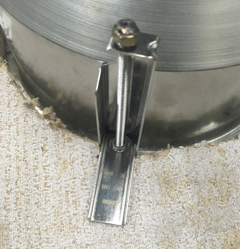
- Using a T20 bit, tighten the mounting arms of the ceiling mount
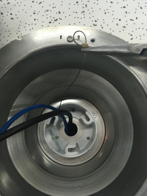
- Pass the Axis MultiCable C I/O and the Ethernet cable through the hole at the top of the camera mount
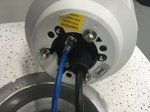
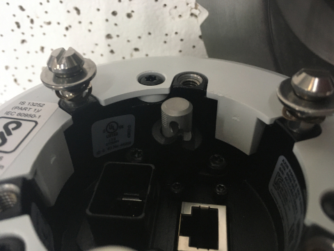
- Connect cables to their respective ports
- Before locking the 5635 to the mounting posts in the ceiling mount, ensure that the safety cable is attached to the camera
- Insert the camera into the ceiling mount and twist until locked in place securely
- Using a T20 bit, secure the dome ring to the camera mount
- Carefully return the ceiling tile to its location
Note: If not using drop ceiling, use alternate instructions inside of the box for mounting to a hard ceiling.
Connecting Wiring
- Begin but cutting two lengths of 22/2. Ensure they are long enough to reach the microphone location. One will be for audio signal. One will be for power.
- Strip the jacket off the 22/2, revealing the red, black, and common (bare wire) on both sides of the cable.
- Remove the string and plastic casings covering the red and black cables.
- Strip the red and black jackets off the wire exposing the copper. Cut copper evenly on both ends. Remove ground.
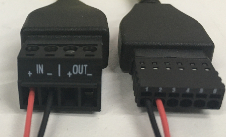
- At the Axis MultiCable C I/O, connect the ends of 22/2
- Audio will be connected to the "In" on the audio terminal block - Red to +, Black to -
- Power will be connected to the I/O terminal block - Red to to 2, Black to 1
