Difference between revisions of "5525 Wall Mount Instructions"
IVSWikiBlue (talk | contribs) |
IVSWikiBlue (talk | contribs) |
||
| Line 34: | Line 34: | ||
#The camera will naturally sit on the base when everything is aligned properly. | #The camera will naturally sit on the base when everything is aligned properly. | ||
#:[[File:Cables through mount.png|250px|link=https://ipivs.com/wiki/images/8/8a/Cables_through_mount.png]] | #:[[File:Cables through mount.png|250px|link=https://ipivs.com/wiki/images/8/8a/Cables_through_mount.png]] | ||
| − | # Take the screws provided with the camera, located in the small box, and secure the camera to the mount using all | + | # Take the screws provided with the camera, located in the small box, and secure the camera to the mount using all 4 screws. |
#:[[File:Camera 2 mount.png|350px|link=https://ipivs.com/wiki/images/4/48/Camera_2_mount.png]] | #:[[File:Camera 2 mount.png|350px|link=https://ipivs.com/wiki/images/4/48/Camera_2_mount.png]] | ||
# | # | ||
Revision as of 08:40, 20 August 2020
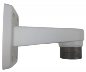
- Locate the AXIS T91E61 Wall Mount.
- This is the recommended wall mount by IVS. Verify the model of your mount here.
- Locate the AXIS T94A01D Pendant Kit.
- Connect the two parts and tighten them together by hand.
- Continue tightening, by hand, until you cannot rotate the pendant kit anymore.
- Using a T20 bit, tighten down the screw located inside the pendant kit.
- Locate the mounting plate.
- This part comes packed with the AXIS M5525.
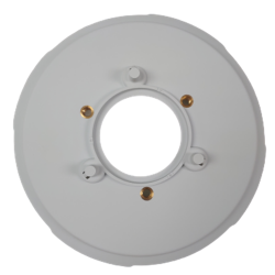
- Take the camera disk and line up the 3 pegs on the top with the three holes on the pendant kit.
- Put the pegs in the holes and rotate the disk counter clockwise until the pieces prevent you from turning more.
- Using a T30 bit, tighten the three screws on top of the pendant kit, securing it to the camera disk.
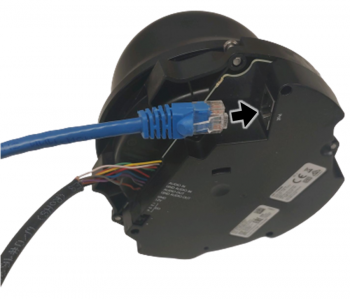
- Take the M5525 and plug the ethernet cable into its respective jack on the camera. The jack will be listed "PoE".
- Please not that only cameras prepared by IVS will have the pigtail wire connected to the camera. To learn more click here
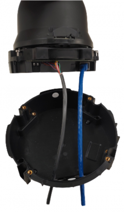
- Remove the rubber grommets from the base of the camera.
- Run the cables through the holes where the grommets were.
- Note that each wire should be in its own hole.
- Once the camera in the base, locate the four screws attached the camera and tighten them using a T20 bit.
- Take the assembled wall mount and run the wires (that are attached to the camera) through the wall mount.
- Match the base of the camera to the bottom of the disc so that the holes for the screws align, allowing the camera to sit comfortably on the mount.
- The camera will naturally sit on the base when everything is aligned properly.
- Take the screws provided with the camera, located in the small box, and secure the camera to the mount using all 4 screws.
-
- [[File:|350px|link=]]
-
- [[File:|350px|link=]]
-
- [[File:|350px|link=]]


