Difference between revisions of "Channel Selector Configuration"
IVSWikiBlue (talk | contribs) |
IVSWikiBlue (talk | contribs) |
||
| Line 39: | Line 39: | ||
[[File:Channel_Selector_Config.png]] | [[File:Channel_Selector_Config.png]] | ||
| + | |||
| + | |||
| + | ==How to Build the Channel Selector== | ||
==Processing Blocks in Tesira== | ==Processing Blocks in Tesira== | ||
| Line 55: | Line 58: | ||
For Compression parameters, click the image below: | For Compression parameters, click the image below: | ||
[[File:Compression_Page.png|link=https://ipivs.com/wiki/Compression_Settings]] | [[File:Compression_Page.png|link=https://ipivs.com/wiki/Compression_Settings]] | ||
| − | |||
| − | |||
| − | |||
Revision as of 16:31, 28 April 2020
Contents
Description/Objective
In this example, there are 16 cameras, each with their own microphone, and an adjacent observation room with 2 OWISP speakers. The customer is also requesting the ability to choose one mic at a time through their overhead speakers, which means we will also build a Canvas User Interface (this will be covered in another section). Before building in Canvas, it is crucial to create the Tesira configuration properly.
Physical Wiring/Line Diagram
Below is the physical wiring diagram, which includes 2 Tesira Forte, a Remote Expander EX/IO, and an Extreme X440 AVB Switch.

Tesira Software
Additional Blocks
- If we've completed our physical connections, open the Tesira software and start building a configuration.
- In this configuration we'll be using the following blocks:
- TesiraFORTE CI block x 2
- Output Block with 4 channels (the remote expander)
- Peak Meter x 7
- Uber Filter x 16
- Level Block with 16 ports and another with 1 port
- Compressor with "ganged mode" and "advanced curve"
- Matrix Mixer with 16 inputs and 16 outputs, with one extra output
- Channel Selector with 16 channels and logic enabled
- 16-channel Logic Meter
- 3 Preset Buttons - two with 8 and another with 1
- Connect the blocks as follows:
- Connect two peak meters to the Tesira Input blocks. This will help us to be sure we have the proper levels set on the preamp.
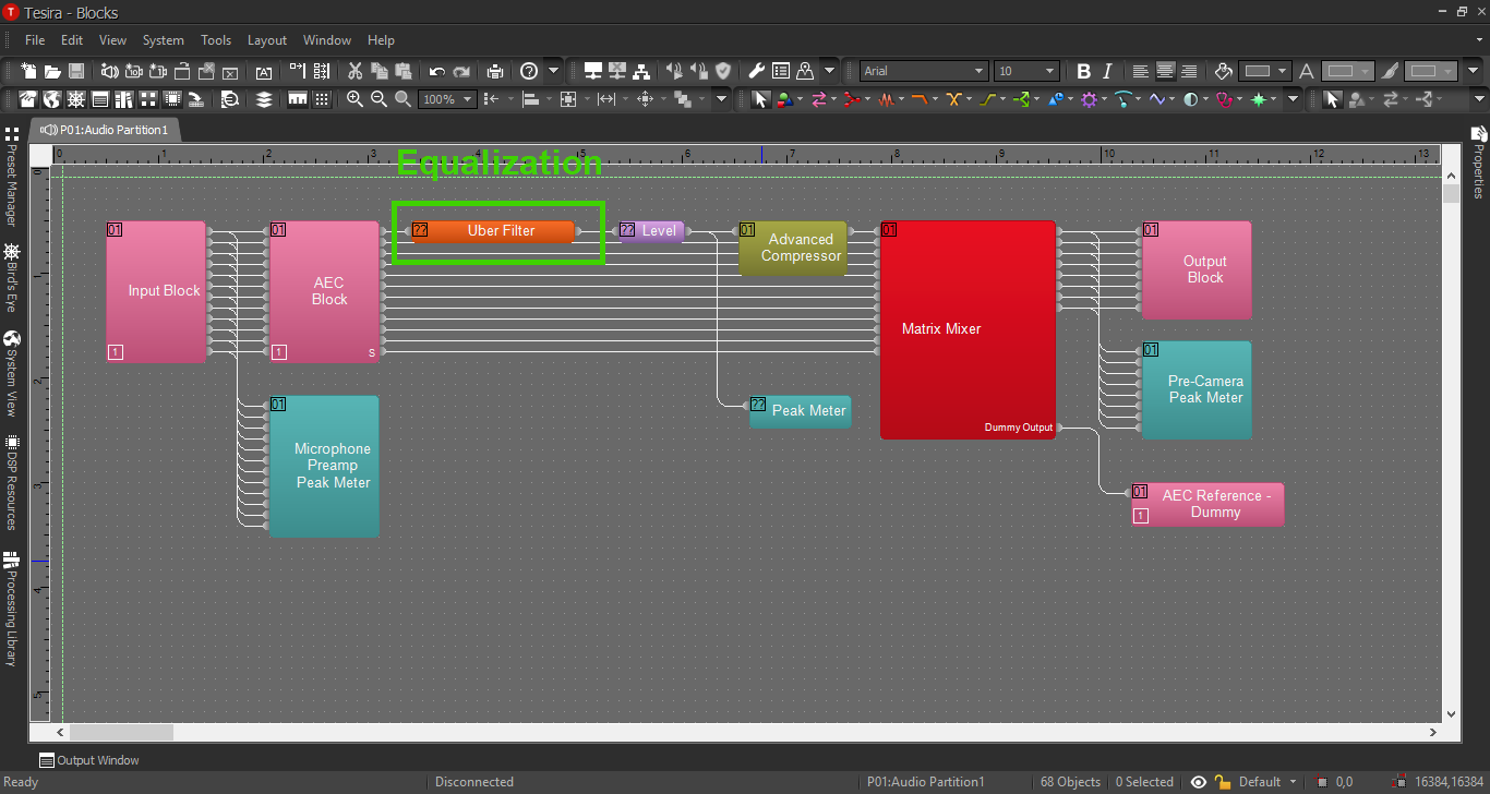
- Connect the AEC block to the Uber Filters, then the Filters to the Level Block.
- Connect the Level Block to the Compressor and two Peak Meters.
- Connect the Compressor to the Matrix Mixer.
- Connect the outputs from the mixer to the Output blocks, peak meters, AND the Channel Selector Block.
- Connect the extra output from the Matrix Mixer to the AEC reference blocks. We will not need to activate the Automatic Echo Cancellation feature in this example.
- Connect the logic output from the Channel Selector to the Logic Meter.
- Place the Preset Blocks in a convenient place for now.
- Send the output of the Channel Selector to the second Level Block, then the level block to the final Peak Meter and the Output Block for the EX/IO Expander.
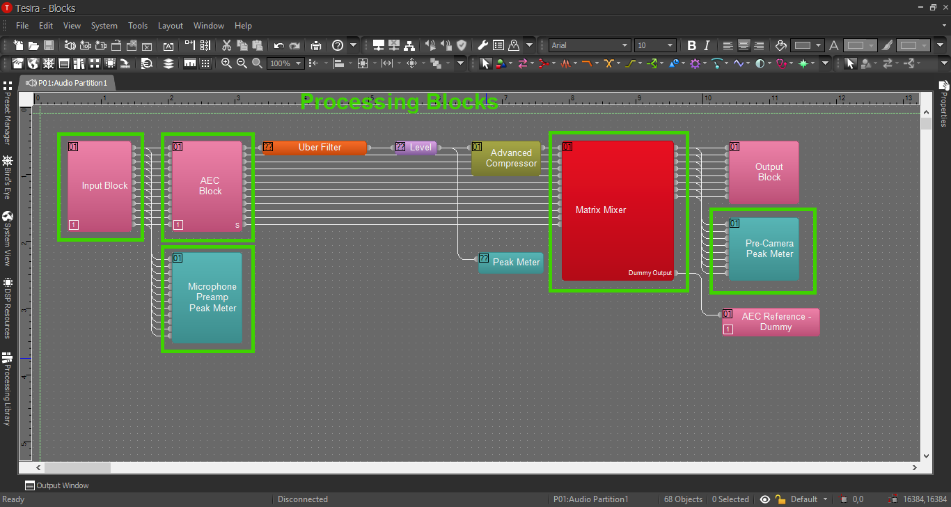
When we're complete, our file should look something like this:

How to Build the Channel Selector
Processing Blocks in Tesira
For further insight about the other processing blocks and settings, refer back to the first configuration example, or click the image below:
EQ and Compression
For information on EQ settings, or click the image below:
For Compression parameters, click the image below:
