Difference between revisions of "Installing an Axis P5635-E with a Louroe Verifact A"
IVSWikiBlue (talk | contribs) (→Installation Instructions) |
IVSWikiBlue (talk | contribs) |
||
| (40 intermediate revisions by the same user not shown) | |||
| Line 1: | Line 1: | ||
| + | {{Wirediagram P5635 Verifact A}} | ||
| + | |||
==Required Parts And Tools== | ==Required Parts And Tools== | ||
* Axis P5635 | * Axis P5635 | ||
| − | |||
* AXIS T94A02L Recessed Mount (If mounting to drop ceiling) | * AXIS T94A02L Recessed Mount (If mounting to drop ceiling) | ||
| − | |||
| − | |||
| − | |||
* 3.5mm (Male to Male) Audio Cable | * 3.5mm (Male to Male) Audio Cable | ||
* Louroe Verifact A Microphone | * Louroe Verifact A Microphone | ||
| − | + | * Axis MultiCable C I/O Audio & Power | |
| − | * Axis MultiCable C I/O Audio & Power | + | * Axis Push-Pull connector |
| − | * | + | * T20 security bit |
| − | * | + | * Wire Stripper |
| − | * Wire Stripper | + | * Tap-Cons (if mounting to concrete) (3/16") |
| − | * | + | * Screws and Anchors (3/16") |
| − | * Anchors | + | * Toggle Bolts (If mounting to drop ceiling tile) (3/16") |
| − | |||
| − | * Toggle Bolts (If mounting to drop ceiling tile) | ||
| − | |||
* Drill bit and drill | * Drill bit and drill | ||
| − | |||
* Phillips head drill bit or Phillips head screwdriver | * Phillips head drill bit or Phillips head screwdriver | ||
| − | * Small Flat head screwdriver | + | * Small Flat head screwdriver (#3) |
| − | + | * Shielded Stranded 22/2 + ground Wire | |
| − | + | * Razor / box cutter | |
| − | * | ||
| − | |||
| − | |||
| − | * Razor | ||
| − | |||
* B-Connectors | * B-Connectors | ||
| − | |||
| − | + | {{P5635 Installation Instructions}} | |
| − | + | {{Connect the Microphone Verifact A}} | |
| − | |||
| − | |||
| − | |||
| − | |||
| − | |||
| − | |||
| − | |||
| − | |||
| − | |||
| − | |||
| − | |||
| − | |||
| − | |||
| − | |||
| − | |||
Latest revision as of 10:48, 18 May 2020
Contents
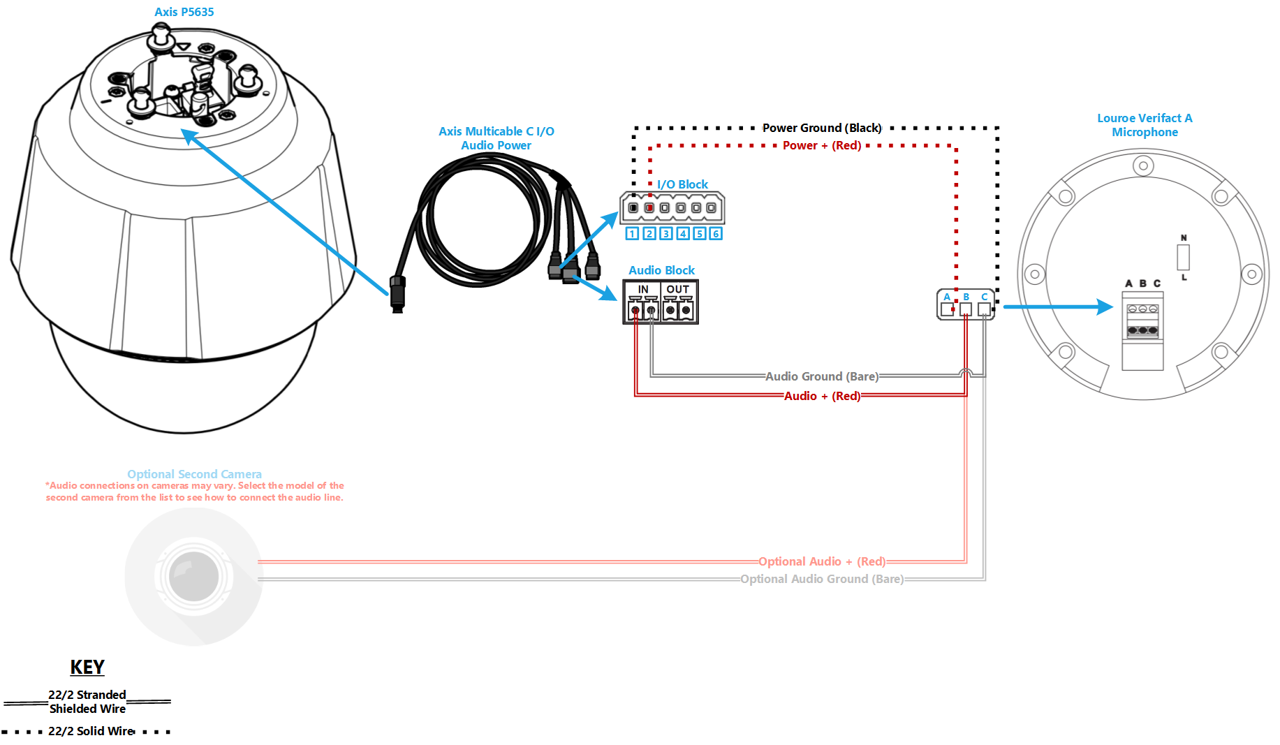
Wiring Diagram
Select Optional Second Camera
![]() Axis P3235
Axis P3235
![]() Axis P3245
Axis P3245
![]() Axis P3364/P3365
Axis P3364/P3365
![]() Axis P3374/P3375
Axis P3374/P3375
![]() Axis Axis F41
Axis Axis F41
![]() Axis P5414/P5415
Axis P5414/P5415
![]() Axis Axis M5525
Axis Axis M5525
![]() Axis Axis P5635
Axis Axis P5635
![]() Axis P5655
Axis P5655
![]() Axis V5914/V5915
Axis V5914/V5915
![]() Axis Q8414
Axis Q8414
Required Parts And Tools
- Axis P5635
- AXIS T94A02L Recessed Mount (If mounting to drop ceiling)
- 3.5mm (Male to Male) Audio Cable
- Louroe Verifact A Microphone
- Axis MultiCable C I/O Audio & Power
- Axis Push-Pull connector
- T20 security bit
- Wire Stripper
- Tap-Cons (if mounting to concrete) (3/16")
- Screws and Anchors (3/16")
- Toggle Bolts (If mounting to drop ceiling tile) (3/16")
- Drill bit and drill
- Phillips head drill bit or Phillips head screwdriver
- Small Flat head screwdriver (#3)
- Shielded Stranded 22/2 + ground Wire
- Razor / box cutter
- B-Connectors
Installation Instructions
Note: There is no need to disassemble the 5635 camera.
Mounting the Camera
- Locate the network drop above the ceiling either being a male Ethernet end (service loop) or a biscuit jack. This will have been ran back to the POE switch.
- Note: If the switch does not have POE, a POE injector will need to be installed at the network closet.
- Remove Axis T94A02L kit from packaging. This will include the mounting bracket and the camera dome ring.
- Determine the location where the 5635 will be mounted and remove the ceiling tile
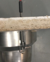
- Measuring the ceiling mount bracket, note that there is a slight lip to the camera mount
-
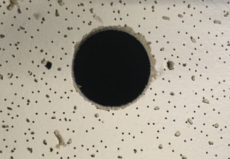
- Find center of the ceiling tile and using a pencil, draw a circle approximately nine inches in diameter
- Using a drywall saw, cut out the section of ceiling tile where the mount will be inserted
-
- Using a T20 bit, tighten the mounting arms of the ceiling mount
-
- Note: Ensure not to over tighten into the ceiling tile.
-
- Pass the Axis MultiCable C I/O and the Ethernet cable through the hole at the top of the camera mount
-
- Connect cables to their respective ports
-
- Before locking the 5635 to the mounting posts in the ceiling mount, ensure that the safety cable is attached to the camera
-
- Insert the camera into the ceiling mount and twist until locked in place securely
-
- Using a T20 bit, secure the dome ring to the camera mount
-
- Carefully return the ceiling tile to its location


Note: If not using drop ceiling, use alternate instructions inside of the box for mounting to a hard ceiling.
Connecting Wiring
- Begin but cutting two lengths of 22/2. Ensure they are long enough to reach the microphone location. One will be for audio signal. One will be for power.
- Strip the jacket off the 22/2, revealing the red, black, and common (bare wire) on both sides of the cable.
- Remove the string and plastic casings covering the red and black cables.
- Strip the red and black jackets off the wire exposing the copper. Cut copper evenly on both ends. Remove ground.
- At the Axis MultiCable C I/O, connect the ends of 22/2
- Audio will be connected to the "In" on the audio terminal block - Red to +, Black to -
- Power will be connected to the I/O terminal block - Red to to 2, Black to 1

Connecting the Microphone
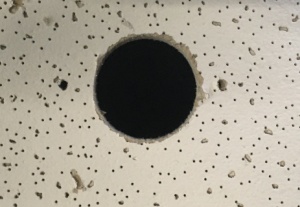
- Mark center of the ceiling tile the Verifact A will be mounted on.
- Using a hole saw, drill a hole at center of the ceiling tile. Feed one end of the the 22/2 cables through the hole.
- Note: Ensure that the hole will be covered by the microphone
-
- Strip the jacket off the 22/2, revealing the red, black, and common (bare wire) on both sides of the cable.
- Remove the string and plastic casings covering the red and black cables.
- Strip the red and black jackets off the wire exposing the copper. Cut copper evenly on both ends. Remove ground.
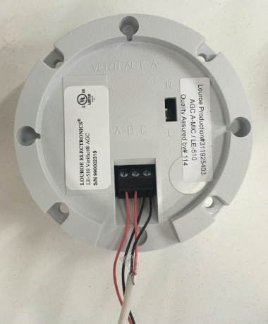
- At the Verifact A, connect the power cable to ports A and C. Connect the audio cable to ports B and C.
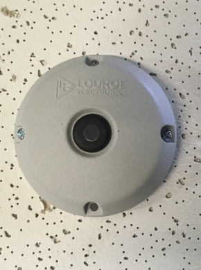
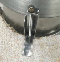
- Using toggle bolts, secure the microphone.
-