Difference between revisions of "Installing an Axis Q8414 with a Louroe Verifact A Microphone"
IVSWikiBlue (talk | contribs) (→Required Parts And Tools) |
IVSWikiBlue (talk | contribs) |
||
| (22 intermediate revisions by the same user not shown) | |||
| Line 1: | Line 1: | ||
| + | {{Wirediagram Q8414 Verifact A}} | ||
| + | |||
==Required Parts And Tools== | ==Required Parts And Tools== | ||
| + | |||
* Axis Q8414 | * Axis Q8414 | ||
| − | |||
| − | |||
* 3.5mm (Male to Male) Audio Cable | * 3.5mm (Male to Male) Audio Cable | ||
| − | * Louroe Verifact A Microphone | + | * Louroe Verifact A Microphone |
| − | * | + | * T20 Torx security bit |
| − | + | * Wire Stripper | |
| − | * Wire Stripper | + | * Tap-Cons (if mounting to concrete) (3/16") |
| − | * | + | * Screws and Anchors (3/16") |
| − | * | + | * Toggle Bolts (If mounting mic to drop ceiling tile)(3/16") |
| − | |||
| − | * Toggle Bolts (If mounting to drop ceiling tile) | ||
| − | |||
* Drill bit and drill | * Drill bit and drill | ||
| − | |||
* Phillips head drill bit or Phillips head screwdriver | * Phillips head drill bit or Phillips head screwdriver | ||
| − | * Small Flat head screwdriver | + | * Small Flat head screwdriver (#3) |
| − | + | * Cat5/6 Patch Cable (7ft-15ft recommended) | |
| − | * Cat5/6 Patch Cable (7ft-15ft recommended) | + | * Shielded Stranded 22/2 + ground Wire |
| − | |||
| − | * 22/2 | ||
| − | |||
==Installation Instructions== | ==Installation Instructions== | ||
| − | #Locate the network drop | + | #Locate the network drop above the ceiling either being a male Ethernet end (service loop) or a biscuit jack. This will have been ran back to the POE switch. If the switch does not have POE, a POE injector will need to be installed at the network closet. |
| − | |||
| − | |||
| − | |||
| − | |||
| − | |||
#Depending on the material of the ceiling, use a 1" paddle bit or a wall dozer to drill a hole in the corner of the ceiling to run the network drop and 3.5 mm audio cable. | #Depending on the material of the ceiling, use a 1" paddle bit or a wall dozer to drill a hole in the corner of the ceiling to run the network drop and 3.5 mm audio cable. | ||
#Remove the camera from the wall mount casing. Remove the gaskets from the back and side panels. With the mount placed in it's install location, make marks for the side and top screws. | #Remove the camera from the wall mount casing. Remove the gaskets from the back and side panels. With the mount placed in it's install location, make marks for the side and top screws. | ||
#Drill holes for the mounting screws. Place the gaskets back into the side holes. | #Drill holes for the mounting screws. Place the gaskets back into the side holes. | ||
#Run the network drop and 3.5 mm audio cable through the ceiling. Secure the mount into place. As you do this, you will want to run the network cable through the top back hole, and the audio cable through the bottom hole. Drill the screws into the side holes, using the washers provided. | #Run the network drop and 3.5 mm audio cable through the ceiling. Secure the mount into place. As you do this, you will want to run the network cable through the top back hole, and the audio cable through the bottom hole. Drill the screws into the side holes, using the washers provided. | ||
| − | #Pull the network and audio cables through the gaskets and drag the gaskets into place in the back holes. | + | #Pull the network and audio cables through the gaskets, and drag the gaskets into place in the back holes. |
| − | #Guide the network and audio cable through the cable tunnels to the back of the camera and plug them in (the pink port is | + | #Guide the network and audio cable through the cable tunnels to the back of the camera, and plug them in (the pink port is AUDIO IN). |
| − | #Carefully adjust the cables, feeding them back into the ceiling if need be, to keep them from being pinched behind the camera as we mount it to the bracket. Make sure the IR window is in the 6 o'clock position; attach the camera using the | + | #Carefully adjust the cables, feeding them back into the ceiling if need be, to keep them from being pinched behind the camera as we mount it to the bracket. Make sure the IR window is in the 6 o'clock position; attach the camera using the T20 bit. |
| − | |||
| − | == | + | ==Connecting the Microphone== |
| − | + | #Drill a hole into the piece of ceiling tile that the Louroe Verifact-A will be mounted to. Feed one end of the the 22/2 audio cable through the hole. Using toggle bolts, secure the microphone. | |
| − | + | #At the microphone, connect the 22/2 cables as follows: '''AUDIO''': Red to B, Black to C '''POWER''': Red to A, Black to C | |
| − | #Drill a hole into the piece of ceiling tile that | + | #At the camera, connect the 22/2 cables as follows: '''AUDIO''': the audio line will be connected to a 3.5mm audio cable (cut approx. 12") with B-connectors, '''POWER''': Red to 3, Black to 1 on I/O terminal block |
| − | # | ||
| − | |||
| − | |||
Latest revision as of 11:05, 18 May 2020
Contents
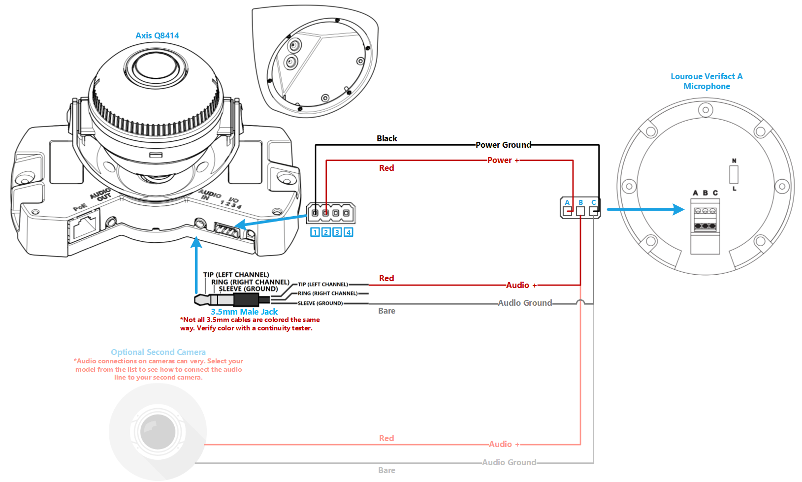
Wiring Diagram
Select Optional Second Camera
![]() Axis P3235
Axis P3235
![]() Axis P3245
Axis P3245
![]() Axis P3364/P3365
Axis P3364/P3365
![]() Axis P3374/P3375
Axis P3374/P3375
![]() Axis Axis F41
Axis Axis F41
![]() Axis P5414/P5415
Axis P5414/P5415
![]() Axis Axis M5525
Axis Axis M5525
![]() Axis Axis P5635
Axis Axis P5635
![]() Axis P5655
Axis P5655
![]() Axis V5914/V5915
Axis V5914/V5915
![]() Axis Q8414
Axis Q8414
Required Parts And Tools
- Axis Q8414
- 3.5mm (Male to Male) Audio Cable
- Louroe Verifact A Microphone
- T20 Torx security bit
- Wire Stripper
- Tap-Cons (if mounting to concrete) (3/16")
- Screws and Anchors (3/16")
- Toggle Bolts (If mounting mic to drop ceiling tile)(3/16")
- Drill bit and drill
- Phillips head drill bit or Phillips head screwdriver
- Small Flat head screwdriver (#3)
- Cat5/6 Patch Cable (7ft-15ft recommended)
- Shielded Stranded 22/2 + ground Wire
Installation Instructions
- Locate the network drop above the ceiling either being a male Ethernet end (service loop) or a biscuit jack. This will have been ran back to the POE switch. If the switch does not have POE, a POE injector will need to be installed at the network closet.
- Depending on the material of the ceiling, use a 1" paddle bit or a wall dozer to drill a hole in the corner of the ceiling to run the network drop and 3.5 mm audio cable.
- Remove the camera from the wall mount casing. Remove the gaskets from the back and side panels. With the mount placed in it's install location, make marks for the side and top screws.
- Drill holes for the mounting screws. Place the gaskets back into the side holes.
- Run the network drop and 3.5 mm audio cable through the ceiling. Secure the mount into place. As you do this, you will want to run the network cable through the top back hole, and the audio cable through the bottom hole. Drill the screws into the side holes, using the washers provided.
- Pull the network and audio cables through the gaskets, and drag the gaskets into place in the back holes.
- Guide the network and audio cable through the cable tunnels to the back of the camera, and plug them in (the pink port is AUDIO IN).
- Carefully adjust the cables, feeding them back into the ceiling if need be, to keep them from being pinched behind the camera as we mount it to the bracket. Make sure the IR window is in the 6 o'clock position; attach the camera using the T20 bit.
Connecting the Microphone
- Drill a hole into the piece of ceiling tile that the Louroe Verifact-A will be mounted to. Feed one end of the the 22/2 audio cable through the hole. Using toggle bolts, secure the microphone.
- At the microphone, connect the 22/2 cables as follows: AUDIO: Red to B, Black to C POWER: Red to A, Black to C
- At the camera, connect the 22/2 cables as follows: AUDIO: the audio line will be connected to a 3.5mm audio cable (cut approx. 12") with B-connectors, POWER: Red to 3, Black to 1 on I/O terminal block