Difference between revisions of "Installing an Axis V5914/V5915 with a Louroe Verifact A Microphone"
IVSWikiBlue (talk | contribs) (→Required Parts And Tools) |
IVSWikiBlue (talk | contribs) |
||
| (5 intermediate revisions by the same user not shown) | |||
| Line 1: | Line 1: | ||
| + | {{Wirediagram V5914 Verifact A}} | ||
| + | |||
==Required Parts And Tools== | ==Required Parts And Tools== | ||
| Line 7: | Line 9: | ||
* Wire Stripper | * Wire Stripper | ||
* Toggle Bolts (If mounting to drop ceiling tile) (3/16") | * Toggle Bolts (If mounting to drop ceiling tile) (3/16") | ||
| − | * | + | * Tap-Cons (if mounting to concrete) (3/16") |
* Screws and Anchors (3/16") | * Screws and Anchors (3/16") | ||
* Drill bit and drill | * Drill bit and drill | ||
| Line 19: | Line 21: | ||
==Installation Instructions== | ==Installation Instructions== | ||
| − | Drop Ceiling Mount | + | ===Drop Ceiling Mount Instructions=== |
'''NOTICE''': The combined weight of the camera and mounting bracket is approximately 1.7 kg (3.7 lb.). Make sure that the ceiling material is strong enough to support this weight. The ceiling tile should be 5–60mm (0.2–2.4in.) thick. | '''NOTICE''': The combined weight of the camera and mounting bracket is approximately 1.7 kg (3.7 lb.). Make sure that the ceiling material is strong enough to support this weight. The ceiling tile should be 5–60mm (0.2–2.4in.) thick. | ||
| − | #Locate the network drop above the ceiling either being a male Ethernet end (service loop) or a biscuit jack. This will have been ran back to the POE switch. If the switch does not have POE, a POE injector will need to be installed at the network closet. | + | #Locate the network drop above the ceiling either being a male Ethernet end (service loop) or a biscuit jack. This will have been ran back to the POE switch. |
| + | #:''Note:'' If the switch does not have POE, a POE injector will need to be installed at the network closet. | ||
#Remove the ceiling tile in which the drop ceiling mount is to be fitted. | #Remove the ceiling tile in which the drop ceiling mount is to be fitted. | ||
#Drill a 7 mm (9/32 in) hole in the ceiling tile. | #Drill a 7 mm (9/32 in) hole in the ceiling tile. | ||
| − | #Drill about a 1" hole where the cables will | + | #Drill about a 1" hole where the cables will pass through into the ceiling. |
#Remove the tripod screw from the mounting bracket. | #Remove the tripod screw from the mounting bracket. | ||
#Attach the short end of the threaded rod to the camera and tighten. | #Attach the short end of the threaded rod to the camera and tighten. | ||
| Line 34: | Line 37: | ||
#Install the ceiling tile with the camera mounted on it. | #Install the ceiling tile with the camera mounted on it. | ||
| − | Wall Mount | + | ===Wall Mount Instructions=== |
| − | #Use a stud finder to locate wall studs, and determine proper placement for the L bracket. Make a mark for the 3 screw holes on the short end of the L bracket, and the area to fish the cables ( | + | #Use a stud finder to locate wall studs, and determine proper placement for the L bracket. |
| − | #Drill | + | #Make a mark for the 3 screw holes on the short end of the L bracket, and the area to fish the cables (3/16" wall screws and anchors used here). |
| − | #Place the anchors | + | #Drill the holes for the anchors |
| + | #Using a hole saw, to drill a hole to fish cables | ||
| + | #Place the anchors and screw the bracket down | ||
| + | #Using glow rods or fish tape, fish the cables (power, network, 3.5mm audio, possible 22/2 for I/O, and possible HDMI cables) down the ceiling through the hole under the bracket. | ||
#Place the V59 onto the bracket, and secure it with the tripod screw from underneath. | #Place the V59 onto the bracket, and secure it with the tripod screw from underneath. | ||
#Route and connect all cables to the camera (network, audio, power, possible HDMI, possible I/O cable). | #Route and connect all cables to the camera (network, audio, power, possible HDMI, possible I/O cable). | ||
| − | == | + | ==Connecting the Microphone== |
#Since the V59 series does not have an I/O terminal block, two separate 22/2 cables will be needed. One for audio and one for power. | #Since the V59 series does not have an I/O terminal block, two separate 22/2 cables will be needed. One for audio and one for power. | ||
#Strip the jacket off the 22/2, revealing the red, black, and common (bare wire) on both sides of the cable. Remove the string and plastic casings covering the red and black cables. Strip the red and black jackets off the wire exposing the copper. Cut copper evenly on both ends (See picture) | #Strip the jacket off the 22/2, revealing the red, black, and common (bare wire) on both sides of the cable. Remove the string and plastic casings covering the red and black cables. Strip the red and black jackets off the wire exposing the copper. Cut copper evenly on both ends (See picture) | ||
#:[[File:Stripped_22_2_Wire.JPG|400x300px]] | #:[[File:Stripped_22_2_Wire.JPG|400x300px]] | ||
| − | #Drill a hole into the piece of ceiling tile that | + | #Drill a hole into the piece of ceiling tile that the Louroe Verifact-A will be mounted to. Feed one end of the the 22/2 audio cables through the hole. Connect the audio cables to the Verifact-A Phoenix terminal as follows; '''AUDIO''': Red to B, Black to C, '''POWER''': Red to A, Black to C. Using Toggle bolts, secure the Verifact-A to the drop ceiling tile. |
| − | #At the camera, the audio line will be ran to the 3.5mm “AUDIO IN” on the Axis V5914/V5915 (See Picture). The power line will be ran and connected to a 12V DC power supply. Use a meter to check line continuity and connect with B connectors. | + | #At the camera, the audio line will be ran to the 3.5mm (cut at approx. 12") “AUDIO IN” on the Axis V5914/V5915 (See Picture). The power line will be ran and connected to a 12V DC power supply. Use a meter to check line continuity and connect with B connectors. |
#:[[File:3.5_to_V5914.JPG|400x300px]] | #:[[File:3.5_to_V5914.JPG|400x300px]] | ||
Latest revision as of 16:39, 18 May 2020
Contents
Wiring Diagram
Select Optional Second Camera
![]() Axis P3235
Axis P3235
![]() Axis P3245
Axis P3245
![]() Axis P3364/P3365
Axis P3364/P3365
![]() Axis P3374/P3375
Axis P3374/P3375
![]() Axis Axis F41
Axis Axis F41
![]() Axis P5414/P5415
Axis P5414/P5415
![]() Axis Axis M5525
Axis Axis M5525
![]() Axis Axis P5635
Axis Axis P5635
![]() Axis P5655
Axis P5655
![]() Axis V5914/V5915
Axis V5914/V5915
![]() Axis Q8414
Axis Q8414
Required Parts And Tools
- Axis V5914/V5915
- 3.5mm (Male to Male) Audio Cable
- Louroe Verifact A Microphone
- T10 Torx bit
- Wire Stripper
- Toggle Bolts (If mounting to drop ceiling tile) (3/16")
- Tap-Cons (if mounting to concrete) (3/16")
- Screws and Anchors (3/16")
- Drill bit and drill
- Phillips head drill bit or Phillips head screwdriver
- Small Flat head screwdriver
- B Connectors
- Cat5/6 Patch Cable (7ft-15ft recommended)
- Shielded Stranded 22/2 + ground Wire
- Fish Tape or Glow Rods
Installation Instructions
Drop Ceiling Mount Instructions
NOTICE: The combined weight of the camera and mounting bracket is approximately 1.7 kg (3.7 lb.). Make sure that the ceiling material is strong enough to support this weight. The ceiling tile should be 5–60mm (0.2–2.4in.) thick.
- Locate the network drop above the ceiling either being a male Ethernet end (service loop) or a biscuit jack. This will have been ran back to the POE switch.
- Note: If the switch does not have POE, a POE injector will need to be installed at the network closet.
- Remove the ceiling tile in which the drop ceiling mount is to be fitted.
- Drill a 7 mm (9/32 in) hole in the ceiling tile.
- Drill about a 1" hole where the cables will pass through into the ceiling.
- Remove the tripod screw from the mounting bracket.
- Attach the short end of the threaded rod to the camera and tighten.
- Assemble the camera, ceiling tile and the mounting bracket, and tighten the nut.
- Route and connect all cables to the camera (network, audio, power, possible HDMI, possible I/O cable).
- Connect the power supply to a mains power outlet (100–240 VAC).
- Install the ceiling tile with the camera mounted on it.
Wall Mount Instructions
- Use a stud finder to locate wall studs, and determine proper placement for the L bracket.
- Make a mark for the 3 screw holes on the short end of the L bracket, and the area to fish the cables (3/16" wall screws and anchors used here).
- Drill the holes for the anchors
- Using a hole saw, to drill a hole to fish cables
- Place the anchors and screw the bracket down
- Using glow rods or fish tape, fish the cables (power, network, 3.5mm audio, possible 22/2 for I/O, and possible HDMI cables) down the ceiling through the hole under the bracket.
- Place the V59 onto the bracket, and secure it with the tripod screw from underneath.
- Route and connect all cables to the camera (network, audio, power, possible HDMI, possible I/O cable).
Connecting the Microphone
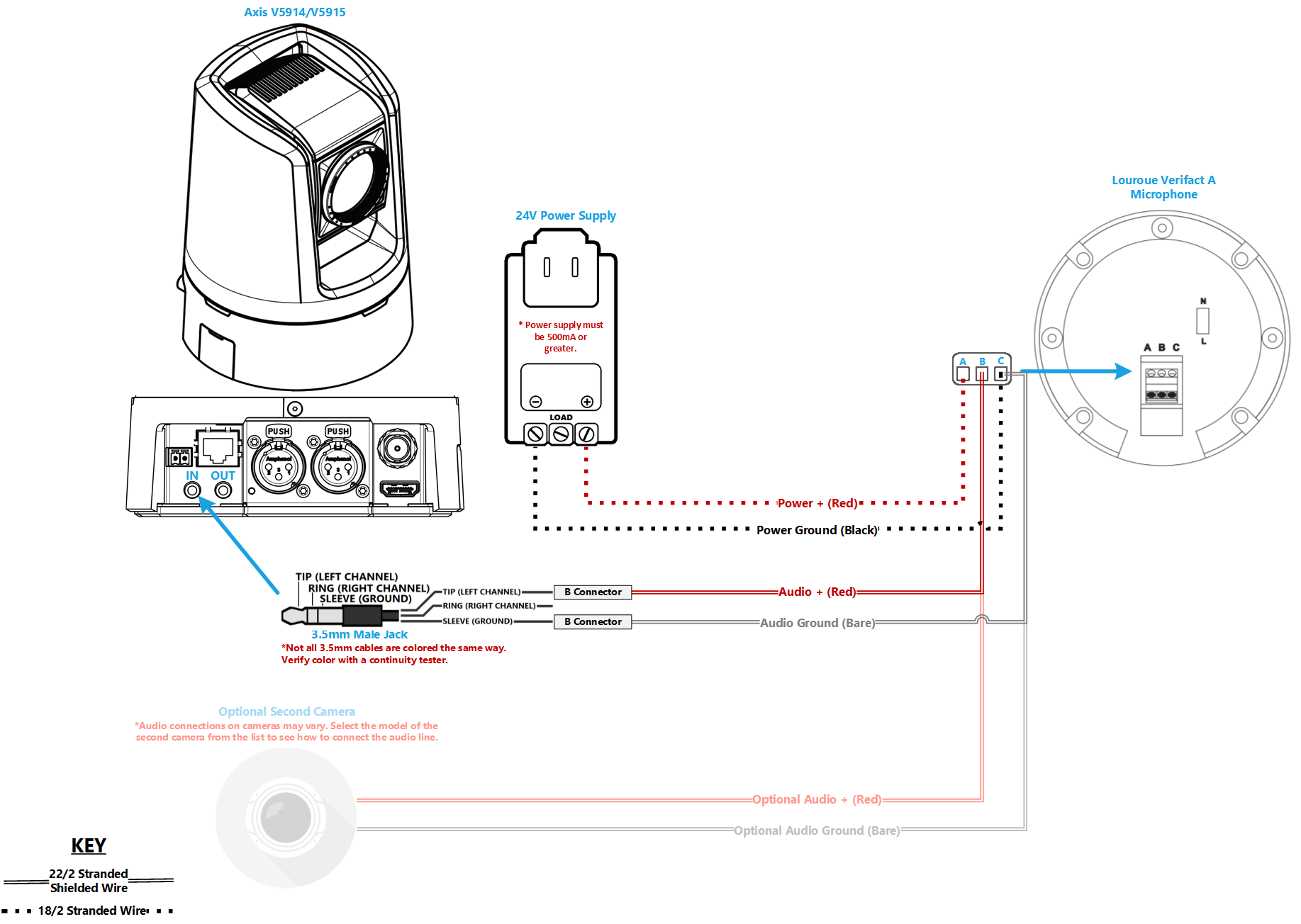
- Since the V59 series does not have an I/O terminal block, two separate 22/2 cables will be needed. One for audio and one for power.
- Strip the jacket off the 22/2, revealing the red, black, and common (bare wire) on both sides of the cable. Remove the string and plastic casings covering the red and black cables. Strip the red and black jackets off the wire exposing the copper. Cut copper evenly on both ends (See picture)
- Drill a hole into the piece of ceiling tile that the Louroe Verifact-A will be mounted to. Feed one end of the the 22/2 audio cables through the hole. Connect the audio cables to the Verifact-A Phoenix terminal as follows; AUDIO: Red to B, Black to C, POWER: Red to A, Black to C. Using Toggle bolts, secure the Verifact-A to the drop ceiling tile.
- At the camera, the audio line will be ran to the 3.5mm (cut at approx. 12") “AUDIO IN” on the Axis V5914/V5915 (See Picture). The power line will be ran and connected to a 12V DC power supply. Use a meter to check line continuity and connect with B connectors.

