Installing an Axis V5914/V5915 with a Sure MX202i Microphone (No Preamp)
Required Parts And Tools
- Axis V5914/V5915
- Shure MX202i Microphone
- 1/2" paddle bit
- 1 blank single gang wall plate
- Toggle Bolts (If mounting to drop ceiling tile) (3/16")
- Wall Dogs (if mounting to concrete) (3/16")
- Screws and Anchors (3/16")
- Drill bit and drill
- Phillips head drill bit or Phillips head screwdriver
- Small Flat head screwdriver
- Hole Saw (2")
- B Connectors
- Cat5/6 Patch Cable (7ft-15ft recommended)
- Shielded Stranded 22/2 + ground Wire
- Fish Tape or Glow Rods
- Wind Screen (Inside MX202i kit)
- Rubber Stopper (Inside MX202i kit)
- 4 pin XLR-M to XLR-M Adapter (Inside MX202i kit)
Installation Instructions
Drop Ceiling Mount WARNING
- The combined weight of the camera and mounting bracket is approximately 1.7 kg (3.7 lb.).
Make sure that the ceiling material is strong enough to support this weight. NOTICE
- The ceiling tile should be 5–60mm (0.2–2.4in.) thick.
- Locate the network drop above the ceiling either being a male Ethernet end (service loop) or a biscuit jack. This will have been ran back to the POE switch. If the switch does not have POE, a POE injector will need to be installed at the network closet.
- Remove the ceiling tile in which the drop ceiling mount is to be fitted.
- Drill a 7 mm (9/32 in) hole in the ceiling tile.
- Remove the tripod screw from the mounting bracket.
- Attach the short end of the threaded rod to the camera and tighten.
- Assemble the camera, ceiling tile and the mounting bracket, and tighten the nut.
- Route and connect all cables to the camera.
- Connect the 4 Pin XLR-M end of the MX202i to the 4 pin XLR-M adapter. Next, run that mic cable to the back of the V59 camera XLR-F input 2 (L).
- Connect the power supply to a mains power outlet (100–240 VAC).
- Install the ceiling tile with the camera mounted on it.
Wall Mount
- Use a stud finder to locate wall studs, and determine proper placement for the L bracket. Make a mark for the 3 screw holes on the short end of the L bracket, and the area to fish the cables. (We will be using 3/16" wall screws and anchors here).
- Drill these holes for the anchors, and use a walldozer to drill a hole to fish the cables.
- Place the anchors, screw the bracket down, and fish our cables (power, network, MX202 XLR-M end, possible 22/2 for I/O, and possible HDMI cables) down the ceiling through the hole under our bracket.
- Place the V59 onto the bracket, and secure it with the tripod screw from underneath.
- Route and connect all cables to the camera (network, audio, power, possible HDMI, possible I/O cable).
- Connect the 4 Pin XLR-M end of the MX202i to the 4 pin XLR-M adapter. Next, run that mic cable to the back of the V59 camera XLR-F input 2 (L).
Connecting and Mounting the Microphone
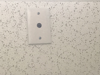
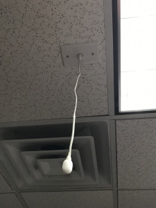
- Using the ½” paddle bit, drill a hole into the center of the single gang plate, and a hole into the desired location for the microphone on your drop ceiling tile. Then secure this single gang plate to the desired location of the microphone on your drop ceiling tile using a pair of toggle bolts. Repeat this process for 2 microphones.
- Run your MX202i through the ½” hole in the ceiling tile and single gang plate. Use the rubber stopper to plug the ½” hole in the single gang plate.
- Lastly, adjust the length of the cable of the microphone to your desired length, hiding the remainder in the ceiling. Attach the windscreen to the MX202i.

