Difference between revisions of "M5525 Shure MX202i W/P"
IVSWikiBlue (talk | contribs) |
IVSWikiBlue (talk | contribs) (→Connecting the STM-) |
||
| (6 intermediate revisions by the same user not shown) | |||
| Line 5: | Line 5: | ||
* RDL STM-1 | * RDL STM-1 | ||
*:[[File:STM-1.JPG|60x80px]] | *:[[File:STM-1.JPG|60x80px]] | ||
| − | |||
| − | |||
* Shure MX202WP/C Microphone | * Shure MX202WP/C Microphone | ||
| − | *:[[File: | + | *:[[File:MX202WPS-large.jpg|60x80px]] |
* Wire Stripper | * Wire Stripper | ||
*:[[File:Wire_Stripper_and_Starbit_Driver.JPG|60x80px]] | *:[[File:Wire_Stripper_and_Starbit_Driver.JPG|60x80px]] | ||
| − | + | ||
| − | |||
| − | |||
| − | |||
| − | |||
| − | |||
| − | |||
| − | |||
| − | |||
* Phillips head drill bit or Phillips head screwdriver | * Phillips head drill bit or Phillips head screwdriver | ||
* Small Flat head screwdriver | * Small Flat head screwdriver | ||
*:[[File:Small_Flathead_Screwdriver.JPG|60x80px]] | *:[[File:Small_Flathead_Screwdriver.JPG|60x80px]] | ||
| − | + | ||
| − | |||
| − | |||
| − | |||
* Stud Finder | * Stud Finder | ||
| − | + | ||
| − | |||
* 22/2 Gauge Wire | * 22/2 Gauge Wire | ||
*:[[File:Audio_Cable.JPG|60x80px]] | *:[[File:Audio_Cable.JPG|60x80px]] | ||
| Line 36: | Line 22: | ||
*Wind Screen (Inside MX202i Box) | *Wind Screen (Inside MX202i Box) | ||
*:[[File:Mic_Windscreen.JPG|60x80px]] | *:[[File:Mic_Windscreen.JPG|60x80px]] | ||
| − | |||
| − | |||
| − | |||
| − | |||
| − | |||
==Connecting the STM-== | ==Connecting the STM-== | ||
| − | + | #Connect MX202WP/C Microphone to the input of the provided wall plate. Connect 22/2 cable to the audio output of that wall plate. VERY IMPORTANT to make the connections AS diagrammed (see below) | |
| − | #Connect | + | #:[[File:202 WP hook up.jpg|400x300px]] |
| − | #:[[File: | + | #Connect the output 22/2 cable to the input of the STM-1 (Red to +, Black to -, bare wire to ground). Connect 22/2 wire to the power of the STM-1 (red to + and black to -). Connect the other end of that cable to the IO Connectors on the M5525 labeled 12V and GND (Red to 12V and BLK to GND). Using 22/2 cable, connect the red and black to the HI-Z output (red to + black to -). Connect the other end of that cable to the to the IO Connectors on the M5525 labled Audio IN and GND (red to Audio IN and Black to GND). Lastly, connect a small jumper wire from the PWR + on the STM-1 to the PHNTM + on the STM-1. (See diagrams below). |
| − | #Connect | + | #:[[File:STM input and phantom.jpg|400x300px]] |
| − | + | #:[[File:Wired STM 1.jpg|400x300px]] | |
| − | + | #:[[File:M5525 connections(1).jpg |400x300px]] | |
| − | #:[[File: | ||
| − | # | ||
| − | #:[[File: | ||
(NOTE; If there are 2 cameras in the room, duplitcate step 9.1.3 using a long enough cable to get to the 2nd camera. If there are 2 Shure MX202i Microphones, duplicate step 9.1.4.) | (NOTE; If there are 2 cameras in the room, duplitcate step 9.1.3 using a long enough cable to get to the 2nd camera. If there are 2 Shure MX202i Microphones, duplicate step 9.1.4.) | ||
Latest revision as of 12:39, 22 March 2018
Required Parts And Tools
- Stud Finder
Connecting the STM-
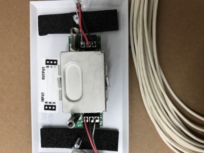
- Connect MX202WP/C Microphone to the input of the provided wall plate. Connect 22/2 cable to the audio output of that wall plate. VERY IMPORTANT to make the connections AS diagrammed (see below)
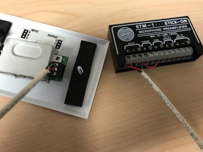
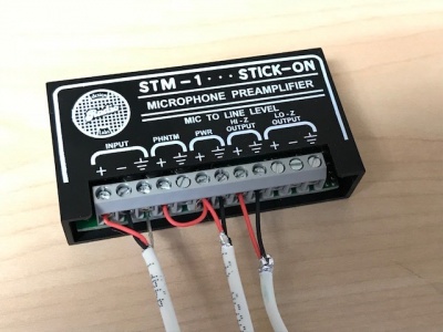
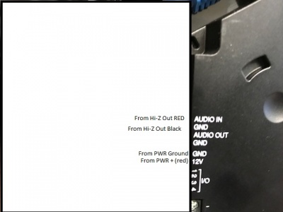
- Connect the output 22/2 cable to the input of the STM-1 (Red to +, Black to -, bare wire to ground). Connect 22/2 wire to the power of the STM-1 (red to + and black to -). Connect the other end of that cable to the IO Connectors on the M5525 labeled 12V and GND (Red to 12V and BLK to GND). Using 22/2 cable, connect the red and black to the HI-Z output (red to + black to -). Connect the other end of that cable to the to the IO Connectors on the M5525 labled Audio IN and GND (red to Audio IN and Black to GND). Lastly, connect a small jumper wire from the PWR + on the STM-1 to the PHNTM + on the STM-1. (See diagrams below).
(NOTE; If there are 2 cameras in the room, duplitcate step 9.1.3 using a long enough cable to get to the 2nd camera. If there are 2 Shure MX202i Microphones, duplicate step 9.1.4.)


