Difference between revisions of "Push-to-talk Talk Back"
IVSWikiBlue (talk | contribs) (→Mounting the Audio) |
IVSWikiBlue (talk | contribs) (→Mounting the Audio) |
||
| Line 25: | Line 25: | ||
#Wire the red to the + and black to the ground power terminals on the STM-1. | #Wire the red to the + and black to the ground power terminals on the STM-1. | ||
#A short piece of 22/2 cable will also be needed (approx. 1 inch). | #A short piece of 22/2 cable will also be needed (approx. 1 inch). | ||
| − | #Strip the jacket from the cable and remove all contents keeping only the red cable. On both ends of the red cable, strip off a piece of the jacket. Connect one end of the 1 inch audio cable to the +PWR terminal and connect the other end into the +PHNTM terminal. | + | #Strip the jacket from the cable and remove all contents keeping only the red cable. |
| + | #On both ends of the red cable, strip off a piece of the jacket. Connect one end of the 1 inch audio cable to the +PWR terminal and connect the other end into the +PHNTM terminal. | ||
#Run another length of 22/2 cable from the STM-1 to the IR T1. Wire red to +, black to -, and bare to ground terminals on the Lo-Z Output on the STM-1. | #Run another length of 22/2 cable from the STM-1 to the IR T1. Wire red to +, black to -, and bare to ground terminals on the Lo-Z Output on the STM-1. | ||
#:''Note:'' If the customer desires to capture the audio from this talkback mic, another run of 22/2 cable will be needed for connecting to a mixer that eventually feeds the camera audio. | #:''Note:'' If the customer desires to capture the audio from this talkback mic, another run of 22/2 cable will be needed for connecting to a mixer that eventually feeds the camera audio. | ||
Revision as of 12:41, 7 May 2020
Contents
Required Parts And Tools
- Williams Talkback System IR T1
- Williams RX224 Receiver
- Shure MX393 Boundary Mic
- RDL STM-1 Preamp
- F-XLR Tail
- 22/2 audio cable
- B-connectors
- Fish Tape or Glow Rods
- Electrical Tape
- Wire Stripper
Installation Instructions
Connecting to the Camera
- Once the camera is installed, locate the AUDIO OUT on your camera
- Strip the jacket of the 22/2 cable revealing the red, black, and bare wires inside.
- Cut away the bare wire and plastic surround the cable inside. Strip away a small piece of the red and black jackets revealing the bare copper wire.
- Wire the black and ground to the - and the red to the + of the AUDIO OUT of phoenix connector.
Mounting the Audio
- Decide where the STM-1 will be located, knowing the MX393 mic will need to reach it.
- Place the MX393. Plug the mic into the F-XLR tail.
- The wires of the XLR will wire to the +, -, and ground Input on the STM-1.
- Note: It may be easier to splice a short length of 22/2 to make it easier to wire to the STM-1 terminals.
- Cut a length of 22/2 from the STM-1 to the camera. Strip the jacket on both ends. Cut away the bare wire and plastic surround the cable inside. Strip away a small piece of the red and black jackets revealing the bare copper wire.
- Wire the red to the + and black to the ground power terminals on the STM-1.
- A short piece of 22/2 cable will also be needed (approx. 1 inch).
- Strip the jacket from the cable and remove all contents keeping only the red cable.
- On both ends of the red cable, strip off a piece of the jacket. Connect one end of the 1 inch audio cable to the +PWR terminal and connect the other end into the +PHNTM terminal.
- Run another length of 22/2 cable from the STM-1 to the IR T1. Wire red to +, black to -, and bare to ground terminals on the Lo-Z Output on the STM-1.
- Note: If the customer desires to capture the audio from this talkback mic, another run of 22/2 cable will be needed for connecting to a mixer that eventually feeds the camera audio.
- Expose the wires on the other end by the IR. Cut a 3.5mm cable open, test for continuity, then splice it with the 22/2 with B-connectors.
- Cover your the splice with electrical tape.
- Plug the 3.5 cable into the Line In of the IR T1.
- Once audio is plugged in, locate the nearest power outlet to power the IR T1.
- Note: You may need to use 18/2 cable to add length to the power cable. Ensure that when splicing in the 18/2 to the power, that the red jacket of the 18/2 is spliced into the cable with the dashed white lines on the power supply.
Testing the System
- Ensure your IR T1 and RX224 are set to the same channel.
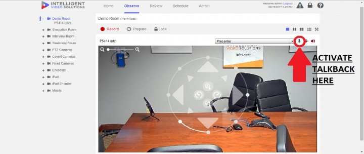
- Test the talkback unit is working by activating the talkback function within the VALT Software and having a partner to communicate with.
