Difference between revisions of "Recording Sign"
IVSWikiBlue (talk | contribs) (→Required Parts and Tools) |
IVSWikiBlue (talk | contribs) (→VALT configuration) |
||
| (6 intermediate revisions by the same user not shown) | |||
| Line 17: | Line 17: | ||
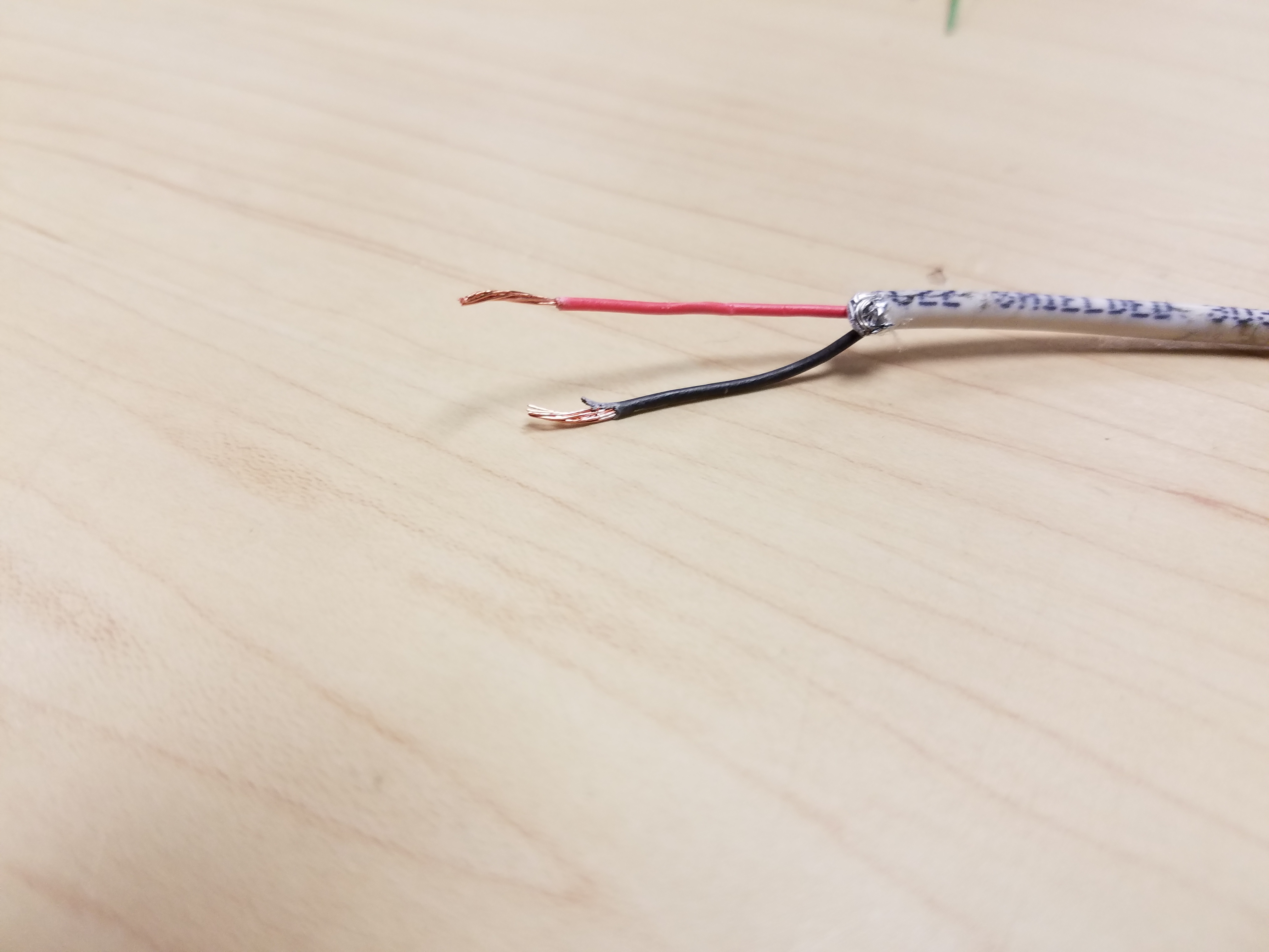
## Strip approximately 1 inch of the outer insulation from each end of the 22/2 wire. | ## Strip approximately 1 inch of the outer insulation from each end of the 22/2 wire. | ||
## Strip approximately 1/4 inch off the insulation for the black and red conductor on each end of the 22/2 wire. | ## Strip approximately 1/4 inch off the insulation for the black and red conductor on each end of the 22/2 wire. | ||
| − | #:: | + | #:: {{img | file = LED4.jpg | width=300px}} |
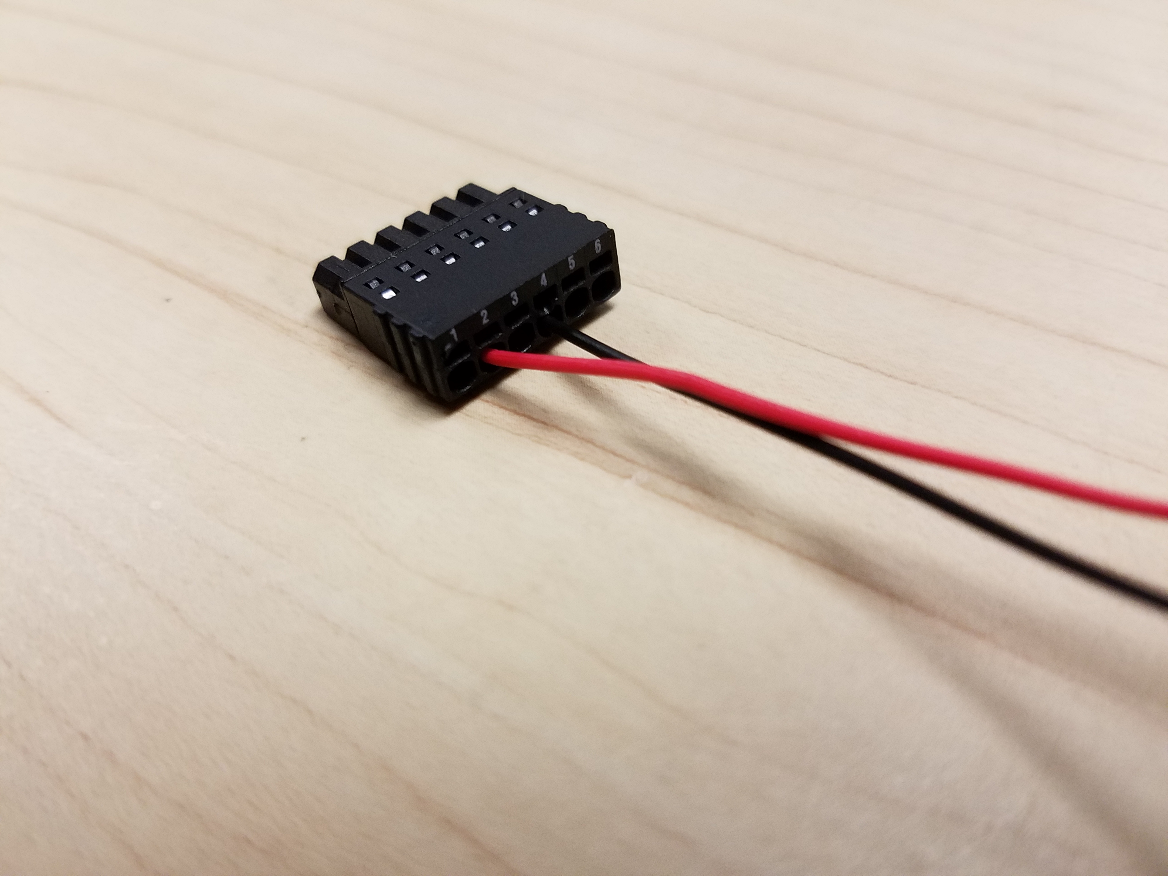
## Insert the red wire into the number 2 I/O port on the camera. If necessary, trim the wire before inserting to ensure no bare wire is exposed. | ## Insert the red wire into the number 2 I/O port on the camera. If necessary, trim the wire before inserting to ensure no bare wire is exposed. | ||
## Insert the black wire into the number 4 I/O port on the camera. If necessary, trim the wire before inserting to ensure no bare wire is exposed. | ## Insert the black wire into the number 4 I/O port on the camera. If necessary, trim the wire before inserting to ensure no bare wire is exposed. | ||
| − | #:: | + | #:: {{img | file = LED3.jpg | width=300px}} |
# Drill holes for your anchors and screws and mount the sign. | # Drill holes for your anchors and screws and mount the sign. | ||
# Connect the 22/2 to the terminal block inside the VALT Recording Sign. | # Connect the 22/2 to the terminal block inside the VALT Recording Sign. | ||
## Strip approximately 1 inch of the outer insulation from each end of the 22/2 wire. | ## Strip approximately 1 inch of the outer insulation from each end of the 22/2 wire. | ||
## Strip approximately 1/2 inch off the insulation for the black and red conductor on each end of the 22/2 wire. | ## Strip approximately 1/2 inch off the insulation for the black and red conductor on each end of the 22/2 wire. | ||
| − | ## Use a jewelers flathead screwdriver to tighten the cable into the terminal block; red with red, black with black. | + | ## Use a jewelers flathead screwdriver to tighten the cable into the terminal block; red with red, black with black. |
== Camera Configuration == | == Camera Configuration == | ||
| Line 33: | Line 33: | ||
#If prompted, enter the username and password for the camera. | #If prompted, enter the username and password for the camera. | ||
#Click on System; click on Ports | #Click on System; click on Ports | ||
| − | #: | + | #: {{img | file = Ports.png}} |
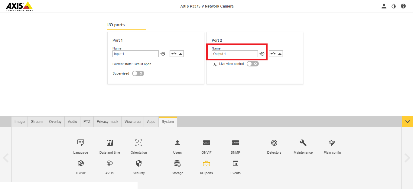
#Ensure that I/O Port 2 is set to Output. | #Ensure that I/O Port 2 is set to Output. | ||
| − | #: | + | #: {{img | file = Port_2.png}} |
== VALT configuration == | == VALT configuration == | ||
| Line 44: | Line 44: | ||
#In the "Command" field, select "Record Indicator". | #In the "Command" field, select "Record Indicator". | ||
#Enter Port number 2. | #Enter Port number 2. | ||
| − | #: | + | #:{{img | file = LED_VALT_config.png}} |
Latest revision as of 11:37, 11 May 2022
Required Parts and Tools
- VALT Recording Sign
- Phillips Screw Driver
- Wire Stripper
- B Connectors
- 22/2 Shielded or Unshielded cable
- Stud Finder
- Hole saw (2")
- Medium Anchors and Screws
- Fish Tape or Glow rods
Installation
- Drill a hole in the sheet rock wall for the 22/2 cable.
- Using fish tape or a wire fish, run 22/2 up through the wall and to the camera.
- Connect the 22/2 to the camera.
- Strip approximately 1 inch of the outer insulation from each end of the 22/2 wire.
- Strip approximately 1/4 inch off the insulation for the black and red conductor on each end of the 22/2 wire.
- Insert the red wire into the number 2 I/O port on the camera. If necessary, trim the wire before inserting to ensure no bare wire is exposed.
- Insert the black wire into the number 4 I/O port on the camera. If necessary, trim the wire before inserting to ensure no bare wire is exposed.
- Drill holes for your anchors and screws and mount the sign.
- Connect the 22/2 to the terminal block inside the VALT Recording Sign.
- Strip approximately 1 inch of the outer insulation from each end of the 22/2 wire.
- Strip approximately 1/2 inch off the insulation for the black and red conductor on each end of the 22/2 wire.
- Use a jewelers flathead screwdriver to tighten the cable into the terminal block; red with red, black with black.
Camera Configuration
Depending on the model of Axis camera, you may need to set the second I/O port on the camera to an output.
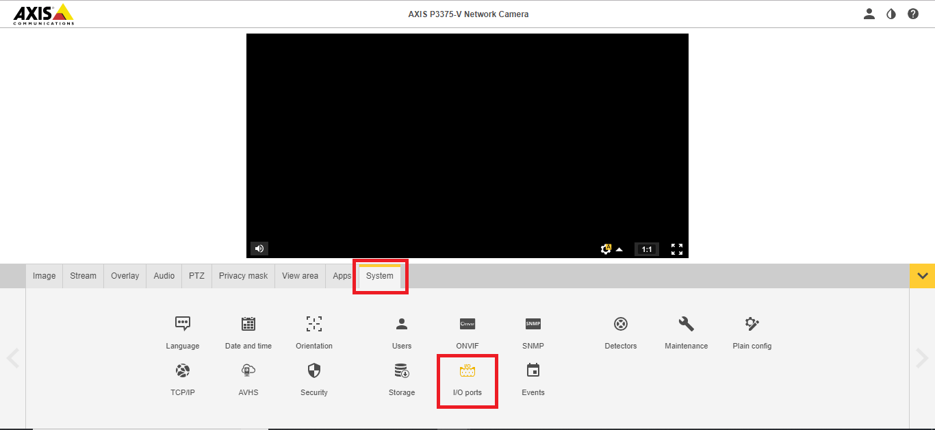
- Navigate to the camera's IP address in a web browser
- If prompted, enter the username and password for the camera.
- Click on System; click on Ports
-
- Ensure that I/O Port 2 is set to Output.
-
VALT configuration
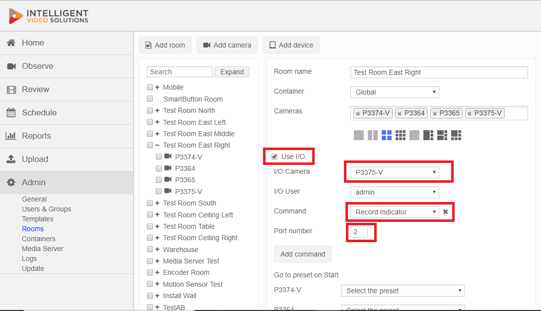
- Head to the Admin Tab.
- Select the room including our camera.
- Check the "Use I/O" box.
- Select the camera in question as the I/O Camera.
- In the "Command" field, select "Record Indicator".
- Enter Port number 2.