Difference between revisions of "Start/Stop Button"
IVSWikiBlue (talk | contribs) |
IVSWikiBlue (talk | contribs) |
||
| (40 intermediate revisions by the same user not shown) | |||
| Line 2: | Line 2: | ||
* IVS Stop/Start Button | * IVS Stop/Start Button | ||
* 22/4 straight wire cable | * 22/4 straight wire cable | ||
| − | * | + | * One single Gang mud ring |
* B-Connectors | * B-Connectors | ||
* Wire Crimper | * Wire Crimper | ||
| Line 10: | Line 10: | ||
* Small Screwdriver | * Small Screwdriver | ||
| − | == | + | ==Wire Diagrams== |
| − | + | Select the button you are installing to see wire diagrams by camera type. | |
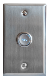
| − | + | [[Start/Stop Diagrams 2020-Present|Start/Stop Diagrams 2020-Present]] | |
| − | + | {{img - button | file = Record Button On.png | link = Start/Stop Diagrams 2020-Present | width=200px}} | |
| − | |||
| − | {| | ||
| − | |||
| − | |||
| − | |- | ||
| − | |||
| − | |||
| − | |||
| − | |||
| − | |||
| − | |||
| − | |||
| − | |||
| − | |||
| − | |||
| − | |||
| − | |} | ||
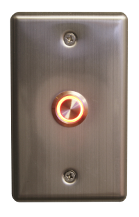
| − | [[ | + | [[Start/Stop Diagrams 2013-2020|Start/Stop Diagrams 2013-2020]] |
| − | + | {{img - button | file = PushButton.png | link = Start/Stop Diagrams 2013-2020 | width=200px}} | |
| − | |||
| − | |||
| − | |||
| − | |||
| − | |||
| − | |||
| − | |||
| − | |||
| − | |||
| − | |||
| − | |||
| − | |||
| − | |||
| − | |||
| − | |||
| − | |||
| − | |||
| − | |||
| − | |||
| − | |||
| − | |||
| − | |||
==Installation Instructions== | ==Installation Instructions== | ||
| Line 64: | Line 25: | ||
#Using a stud finder, scan the mounting location of the button to ensure it is not mounted on a stud. | #Using a stud finder, scan the mounting location of the button to ensure it is not mounted on a stud. | ||
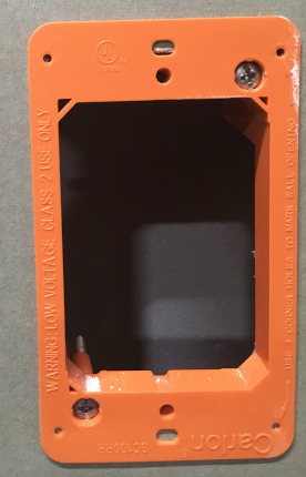
#Cut a hole into the drywall, large enough to fit the mud ring into it securely. | #Cut a hole into the drywall, large enough to fit the mud ring into it securely. | ||
| − | #: | + | #: {{img | file = VerifactDring.JPG | width=130px}} |
#Using a hole saw or drywall saw, drill a hole above the drop ceiling in line with the hole drilled where the button is mounted. | #Using a hole saw or drywall saw, drill a hole above the drop ceiling in line with the hole drilled where the button is mounted. | ||
#Using fish tape or glow rods, pass the 22/4 through the drywall | #Using fish tape or glow rods, pass the 22/4 through the drywall | ||
#At the button, use B-Connectors to connect the button | #At the button, use B-Connectors to connect the button | ||
| − | #*Black to Black, White to White, Red to Red, Green to | + | #*Black to Black, White to White, Red to Red, Green to Green (please reference camera diagrams above) |
| − | #At the camera, connect the | + | #At the camera, connect the 22/4 to the I/O port of the camera (please reference camera diagrams above) |
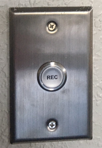
#Once connected, mount the face plate to the mud ring. Make sure face plate is level | #Once connected, mount the face plate to the mud ring. Make sure face plate is level | ||
#Follow the instructions below to configure the button and click to test. | #Follow the instructions below to configure the button and click to test. | ||
| − | #: | + | #: {{img | file = StartStopMounted.jpg | width=130px}} |
==Software Configuration== | ==Software Configuration== | ||
| Line 78: | Line 39: | ||
Log into the software with admin rights and navigate to the Admin section then click on Rooms. | Log into the software with admin rights and navigate to the Admin section then click on Rooms. | ||
| − | + | {{img | file = Start_stop_config.png | width=1200px}} | |
#) Select the room. | #) Select the room. | ||
#) Check the '''Use I/O''' box. | #) Check the '''Use I/O''' box. | ||
| Line 95: | Line 56: | ||
Log into VALT as an admin and click the Admin tab | Log into VALT as an admin and click the Admin tab | ||
| − | + | {{img | file = ValtAdminTab.png | width=1200px}} | |
Click on Users and Groups and click on the IO Group | Click on Users and Groups and click on the IO Group | ||
| − | + | {{img | file = ValtUserGroups.png | width=1200px}} | |
Scroll to the bottom and click the Check all on the video access | Scroll to the bottom and click the Check all on the video access | ||
| − | + | {{img | file = ValtVideoAccess.png}} | |
==Camera Configuration== | ==Camera Configuration== | ||
| Line 110: | Line 71: | ||
#) Go to '''Setup''' in the top right; then '''System Options'''. | #) Go to '''Setup''' in the top right; then '''System Options'''. | ||
#) For '''Allow Password Type''', select '''Unencrypted Only'''. | #) For '''Allow Password Type''', select '''Unencrypted Only'''. | ||
| − | #: | + | #:{{img | file = Start_stop_unencrypt.png}} |
#) Navigate to '''Ports & Devices'''. | #) Navigate to '''Ports & Devices'''. | ||
#) Change Ports 2 & 4 to '''Output''' (if it hasn't already been done). | #) Change Ports 2 & 4 to '''Output''' (if it hasn't already been done). | ||
| − | #: | + | #:{{img | file = Ports_old.png}} |
====In the new navigation view==== | ====In the new navigation view==== | ||
#) Go to '''Settings'''; then '''System'''; then '''Plain Config'''. | #) Go to '''Settings'''; then '''System'''; then '''Plain Config'''. | ||
| − | #: | + | #:{{img | file = Start_stop_unencrypt_new.png}} |
#) Scroll and select '''Network'''. | #) Scroll and select '''Network'''. | ||
#) Under '''HTTP''', '''Authentication Policy''', select '''Basic'''. Scroll to click '''Save'''. | #) Under '''HTTP''', '''Authentication Policy''', select '''Basic'''. Scroll to click '''Save'''. | ||
| − | #: | + | #:{{img | file = Start_stop_unencrypt_new_2.png}} |
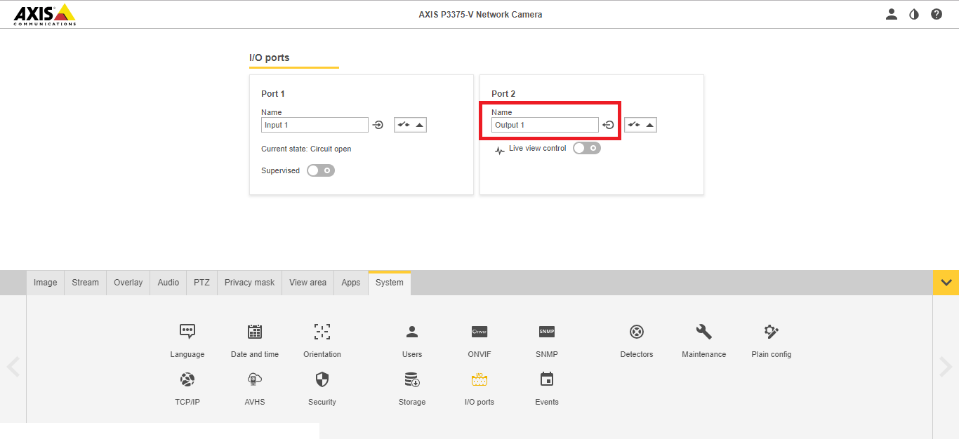
#) Also head to '''System''' > '''I/O Ports'''. | #) Also head to '''System''' > '''I/O Ports'''. | ||
| − | #: | + | #:{{img | file = Ports.png}} |
#) Change Port 2 to '''Output'''. | #) Change Port 2 to '''Output'''. | ||
| − | #: | + | #:{{img | file = Port_2.png}} |
| − | ''Note:'' If after proper configuration the button does not appear to function, the Wowza | + | ''Note:'' If after proper configuration the button does not appear to function, the Wowza Streaming Engine service likely needs to be restarted. |
Latest revision as of 08:42, 26 October 2022
Contents
Required Parts and Tools
- IVS Stop/Start Button
- 22/4 straight wire cable
- One single Gang mud ring
- B-Connectors
- Wire Crimper
- Stud finder
- Fish tape or Glow Rods
- Face plate screws
- Small Screwdriver
Wire Diagrams
Select the button you are installing to see wire diagrams by camera type.
Start/Stop Diagrams 2020-Present
Installation Instructions
- Determine if the button will be mounted outside or inside the associated room. If mounting near light switches or other control devices, match the mount height of those devices.
- Using a stud finder, scan the mounting location of the button to ensure it is not mounted on a stud.
- Cut a hole into the drywall, large enough to fit the mud ring into it securely.
-
- Using a hole saw or drywall saw, drill a hole above the drop ceiling in line with the hole drilled where the button is mounted.
- Using fish tape or glow rods, pass the 22/4 through the drywall
- At the button, use B-Connectors to connect the button
- Black to Black, White to White, Red to Red, Green to Green (please reference camera diagrams above)
- At the camera, connect the 22/4 to the I/O port of the camera (please reference camera diagrams above)
- Once connected, mount the face plate to the mud ring. Make sure face plate is level
- Follow the instructions below to configure the button and click to test.
-
Software Configuration
Log into the software with admin rights and navigate to the Admin section then click on Rooms.
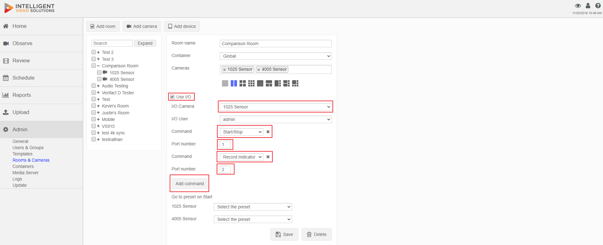
- ) Select the room.
- ) Check the Use I/O box.
- ) Select what camera the I/O wiring is tied into.
- ) Select a user - All I/O recordings in that room will be considered authored by that user.
- ) Select Start/Stop in the command field.
- ) Enter Port Number 1.
- ) Click Add Command.
- ) Select Record Indicator in the command field.
- ) Enter Port Number 2.
- ) If it is a PTZ camera, the camera may be assigned to a preset at the start of the recording.
- ) Press Save to enable I/O button recordings.
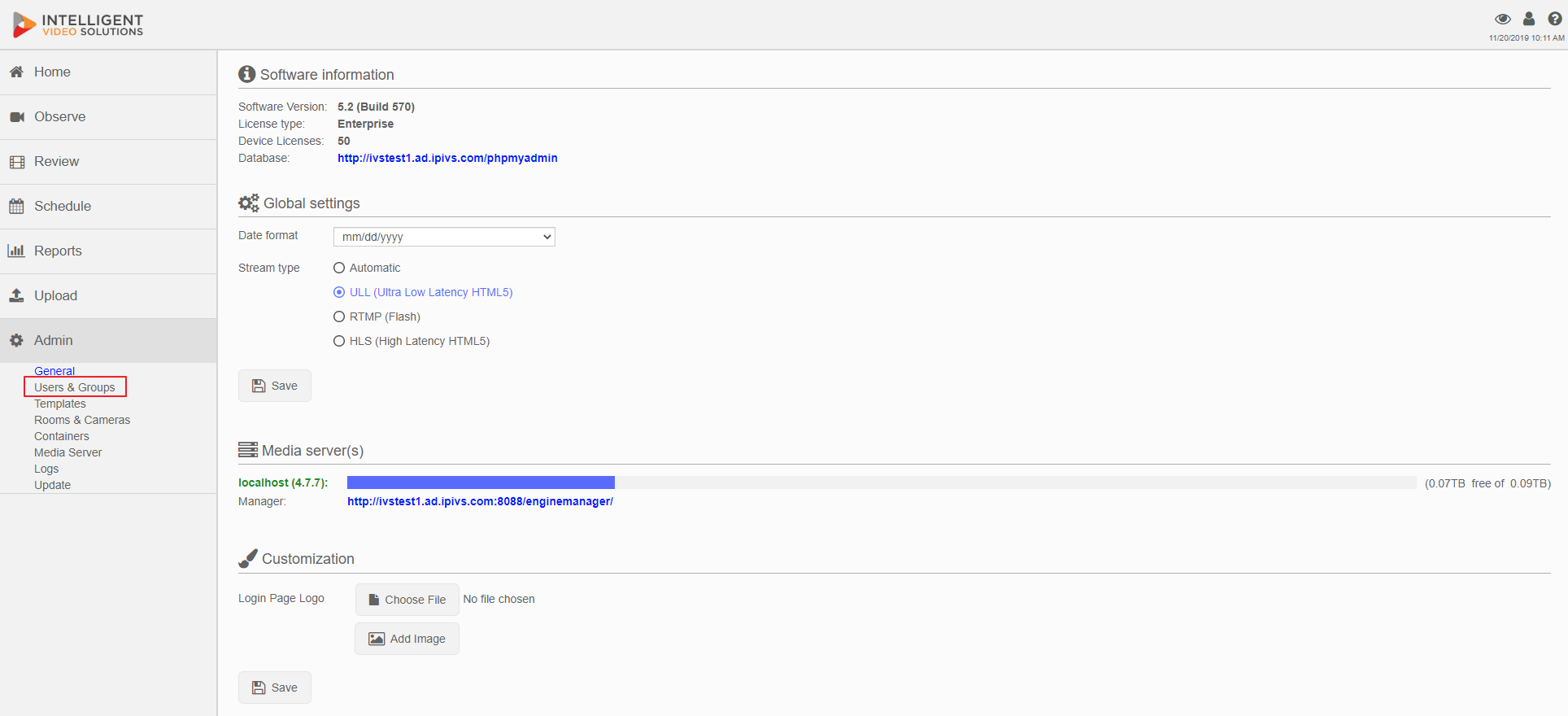
In the User Groups make sure the I/O User's group has video access to every group
Log into VALT as an admin and click the Admin tab
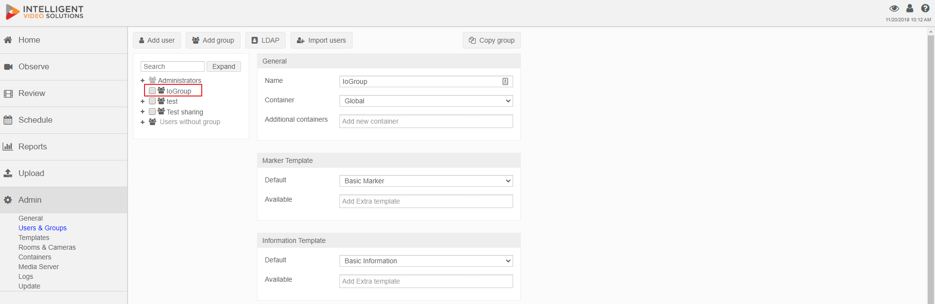
Click on Users and Groups and click on the IO Group
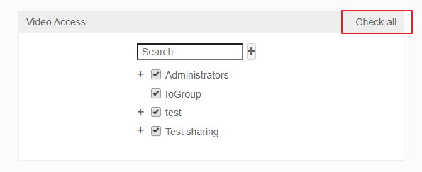
Scroll to the bottom and click the Check all on the video access
Camera Configuration
- ) Navigate to the IP of the camera.
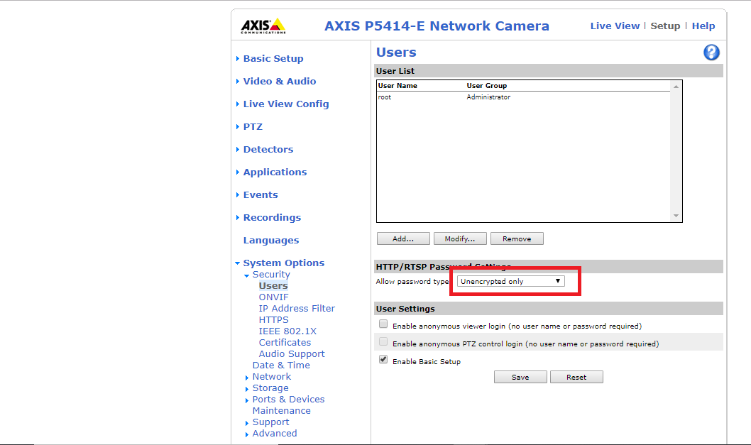
- ) Go to Setup in the top right; then System Options.
- ) For Allow Password Type, select Unencrypted Only.
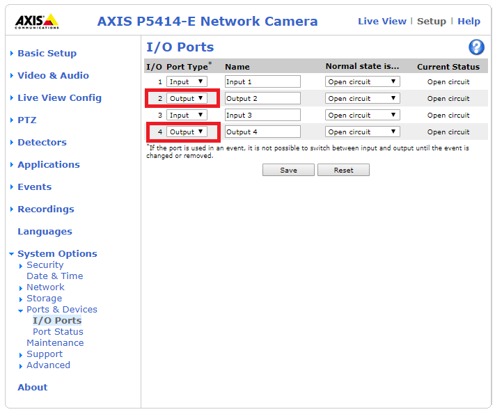
- ) Navigate to Ports & Devices.
- ) Change Ports 2 & 4 to Output (if it hasn't already been done).
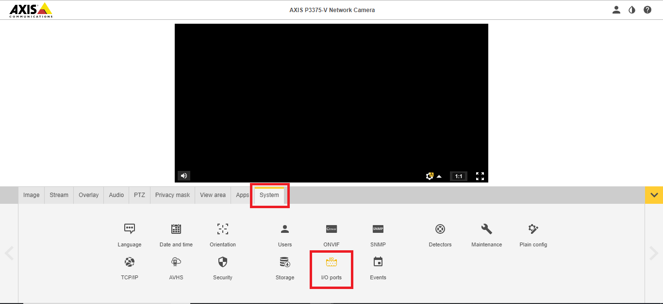
- ) Go to Settings; then System; then Plain Config.
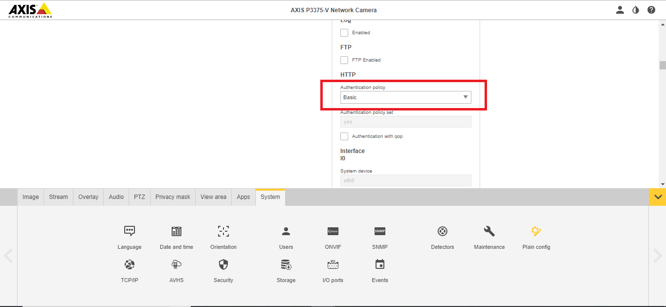
- ) Scroll and select Network.
- ) Under HTTP, Authentication Policy, select Basic. Scroll to click Save.
- ) Also head to System > I/O Ports.
- ) Change Port 2 to Output.

Note: If after proper configuration the button does not appear to function, the Wowza Streaming Engine service likely needs to be restarted.