Difference between revisions of "Tubular LED Key Switch"
IVSWikiBlue (talk | contribs) |
IVSWikiBlue (talk | contribs) |
||
| Line 9: | Line 9: | ||
* Fish Tape or Glow Rod [[File:15-4-57-m-mid-flex-glow-rod-set-tools-to-k56415-to-k56415-19671-228x228.jpg|60x80px]] | * Fish Tape or Glow Rod [[File:15-4-57-m-mid-flex-glow-rod-set-tools-to-k56415-to-k56415-19671-228x228.jpg|60x80px]] | ||
* DryWall Saw [[File:DryWall_Saw.JPG|60x80px]] | * DryWall Saw [[File:DryWall_Saw.JPG|60x80px]] | ||
| − | * Mud Ring [[File:Mud_Ring.JPG|60x80px] | + | * Mud Ring [[File:Mud_Ring.JPG|60x80px] |
| − | |||
==Installation Instructions== | ==Installation Instructions== | ||
Revision as of 13:28, 5 January 2017
Required Parts And Tools
- Securitron KP-1
- Wire Stripper
- Small Flat head screwdriver
- B Connectors

- Stud Finder
- 22/4 Solid Gauge Wire
- Fish Tape or Glow Rod

- DryWall Saw
- Mud Ring [[File:Mud_Ring.JPG|60x80px]
Installation Instructions
- Locate the network drop that is ran back to the HIGH POE switch. (If the switch does not have HIGH POE, you will need to insert a HIGH POE injector back at the network closet).
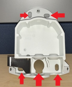
- Remove the P5414/P5415 camera from its base with the starbit security driver. Place the base of the camera on the wall where you’d like to mount. Using a stud finder, ensure there aren’t any studs any behind the camera base. Using a marker or pen, mark the 4 areas on the wall where the screws would be and also mark the opening where the any cabling would come through (Areas labeled on picture).


