Difference between revisions of "Tubular LED Key Switch"
IVSWikiBlue (talk | contribs) |
IVSWikiBlue (talk | contribs) |
||
| (11 intermediate revisions by the same user not shown) | |||
| Line 1: | Line 1: | ||
==Required Parts And Tools== | ==Required Parts And Tools== | ||
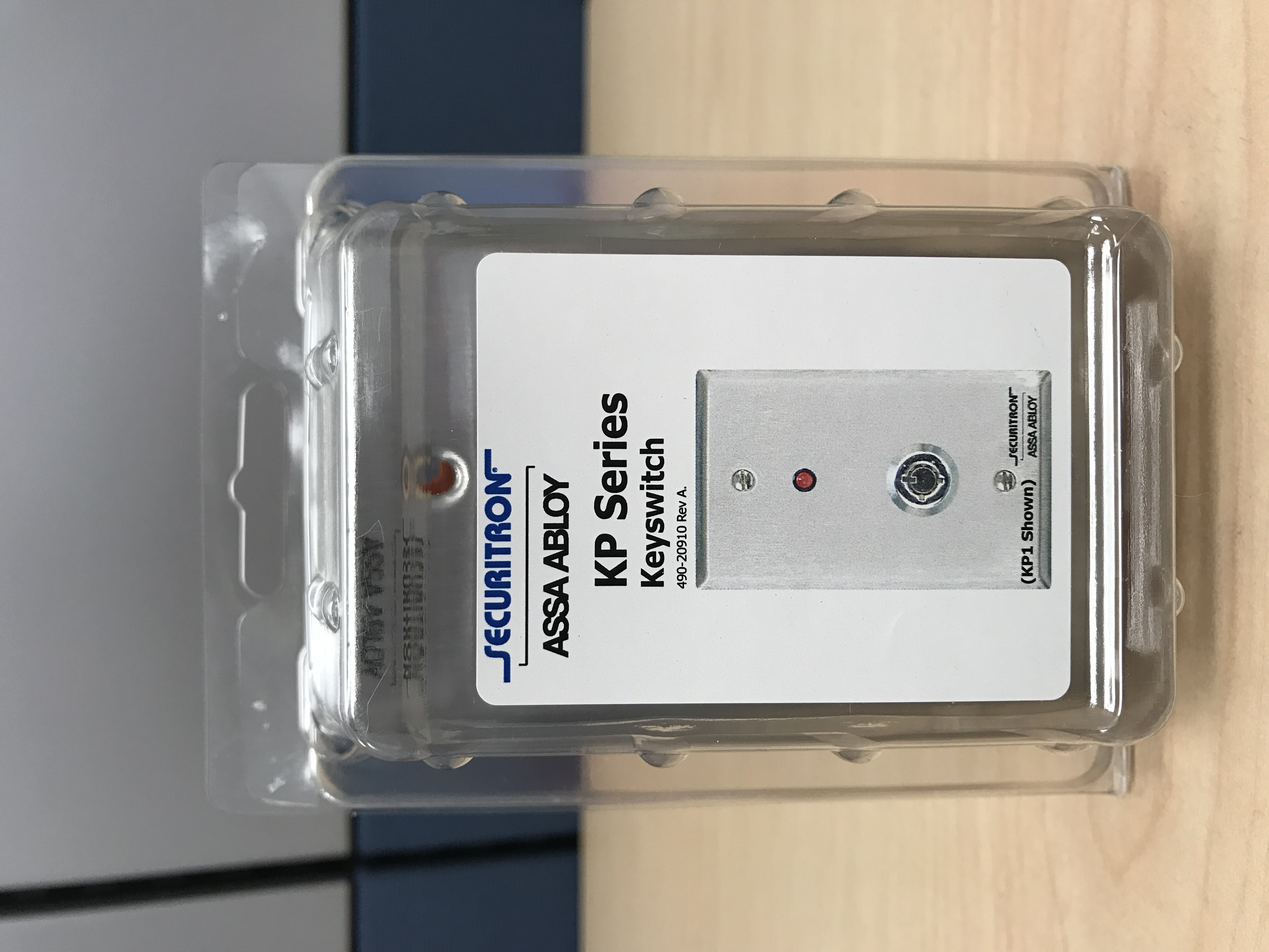
| − | * Securitron KP-1 | + | * Securitron KP-1 |
| − | * Wire Stripper | + | :{{img | file = Securitron KP1.JPG | width=80px}} |
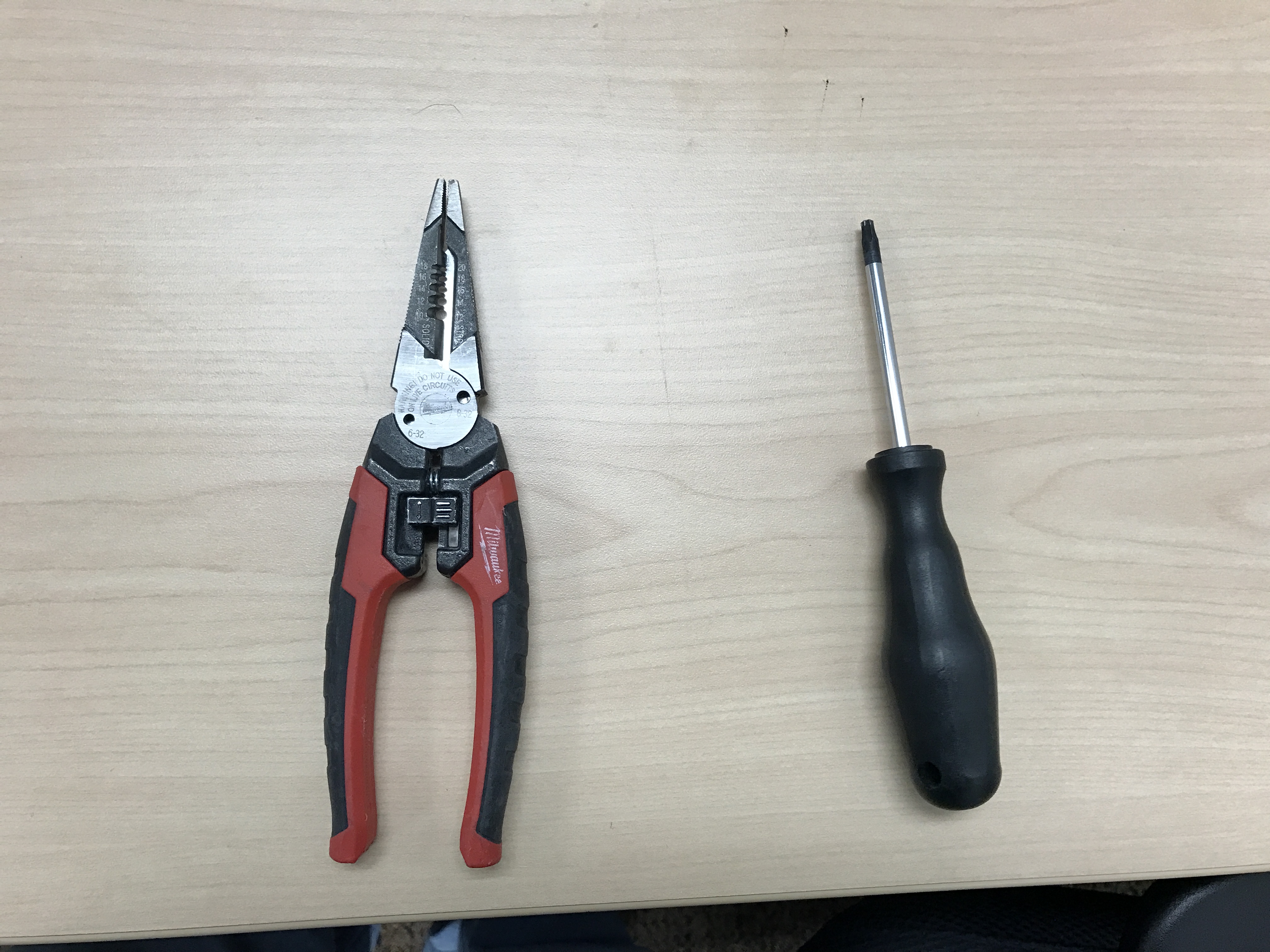
| − | * Small Flat head screwdriver | + | * Wire Stripper |
| − | * B Connectors | + | :{{img | file = Wire_Stripper_and_Starbit_Driver.JPG | width=80px}} |
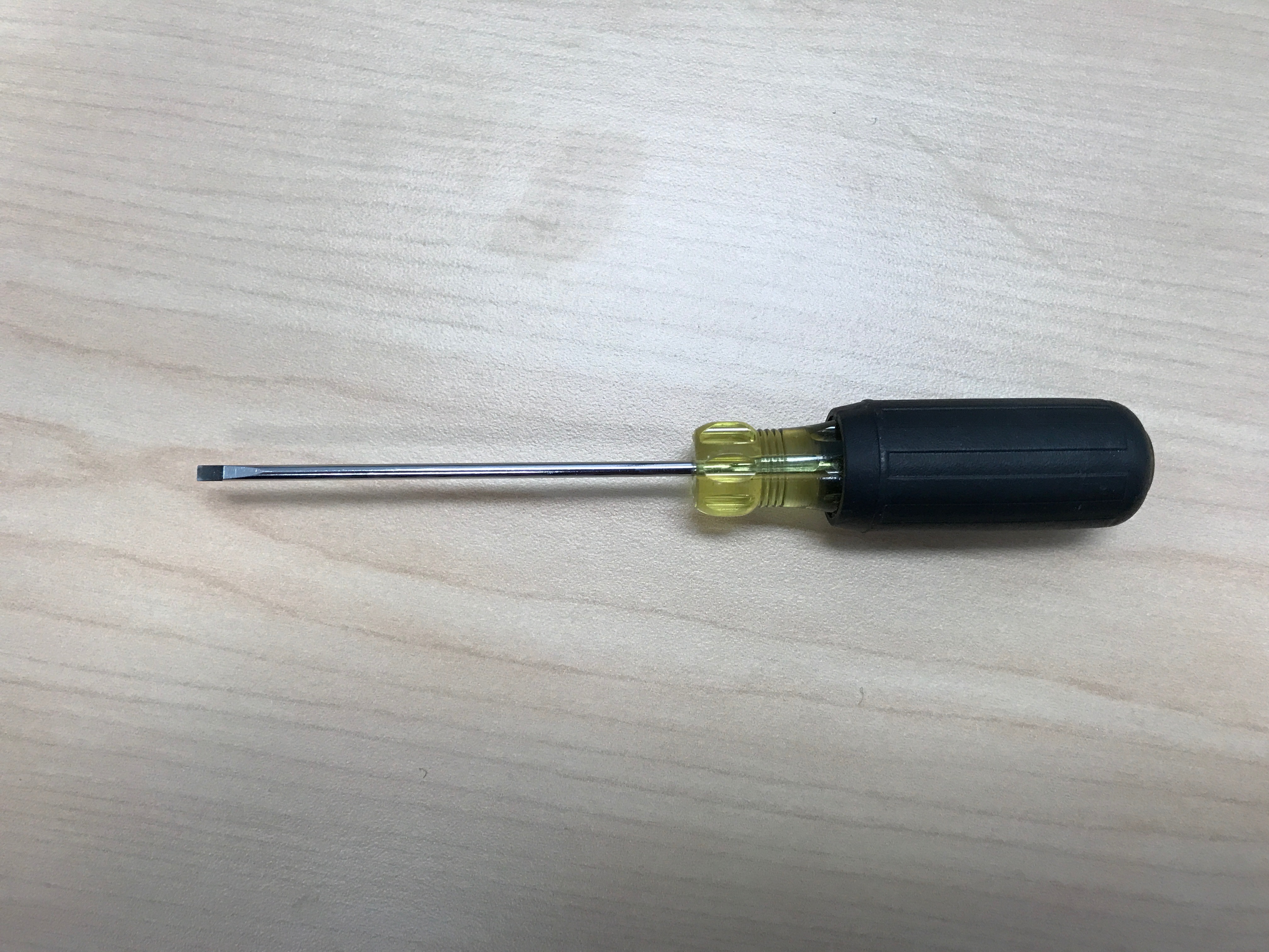
| + | * Small Flat head screwdriver | ||
| + | :{{img | file = Small_Flathead_Screwdriver.JPG | width=80px}} | ||
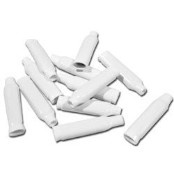
| + | * B Connectors | ||
| + | :{{img | file = BCONN.png | width=80px}} | ||
* Stud Finder | * Stud Finder | ||
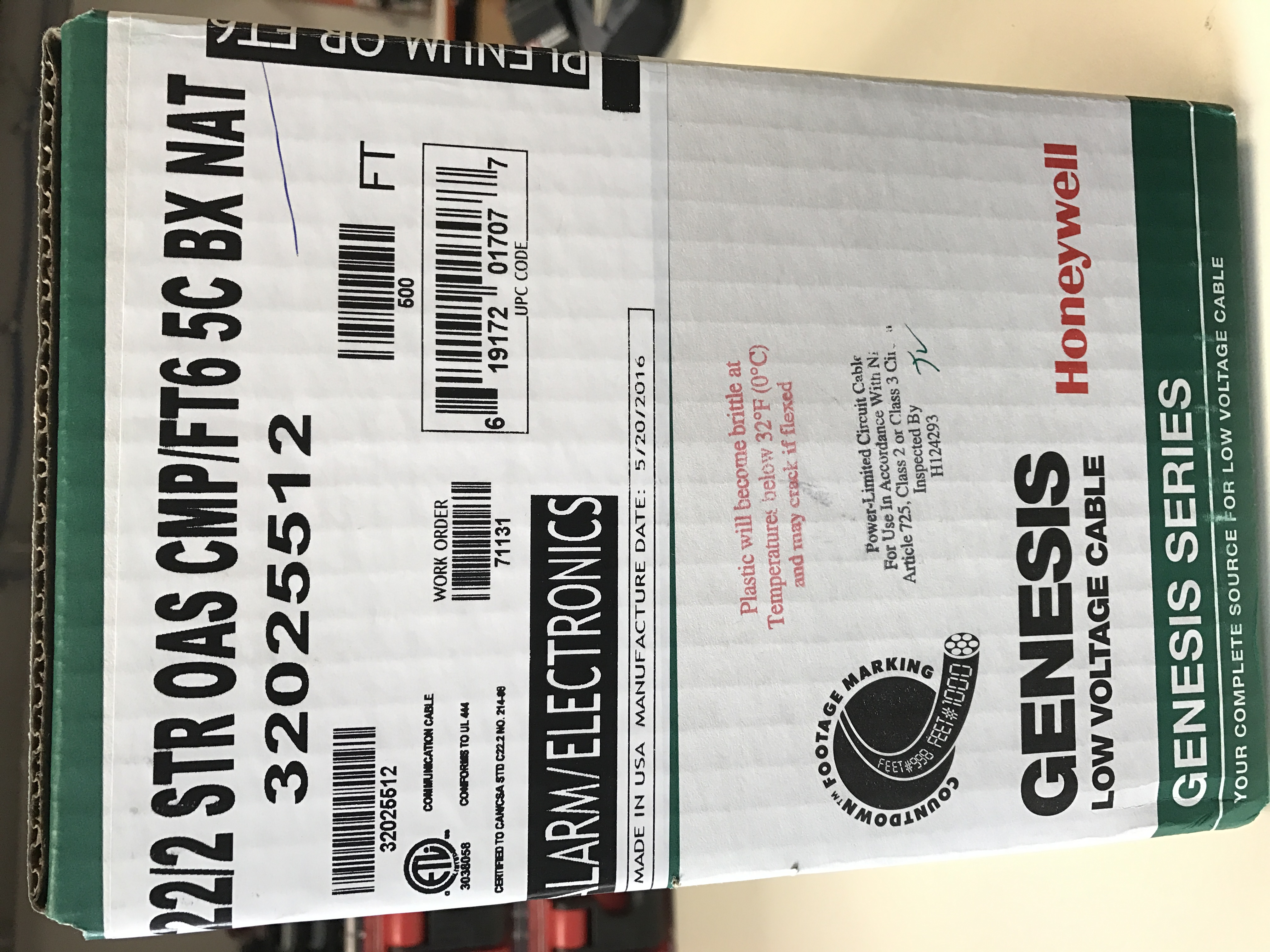
| − | * 22/4 Solid Gauge Wire | + | * 22/4 Solid Gauge Wire |
| − | * Fish Tape or Glow Rod | + | :{{img | file = Audio_Cable.JPG | width=80px}} |
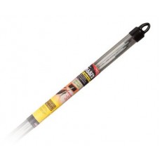
| − | * DryWall Saw | + | * Fish Tape or Glow Rod |
| − | * Mud Ring | + | :{{img | file = 15-4-57-m-mid-flex-glow-rod-set-tools-to-k56415-to-k56415-19671-228x228.jpg | width=80px}} |
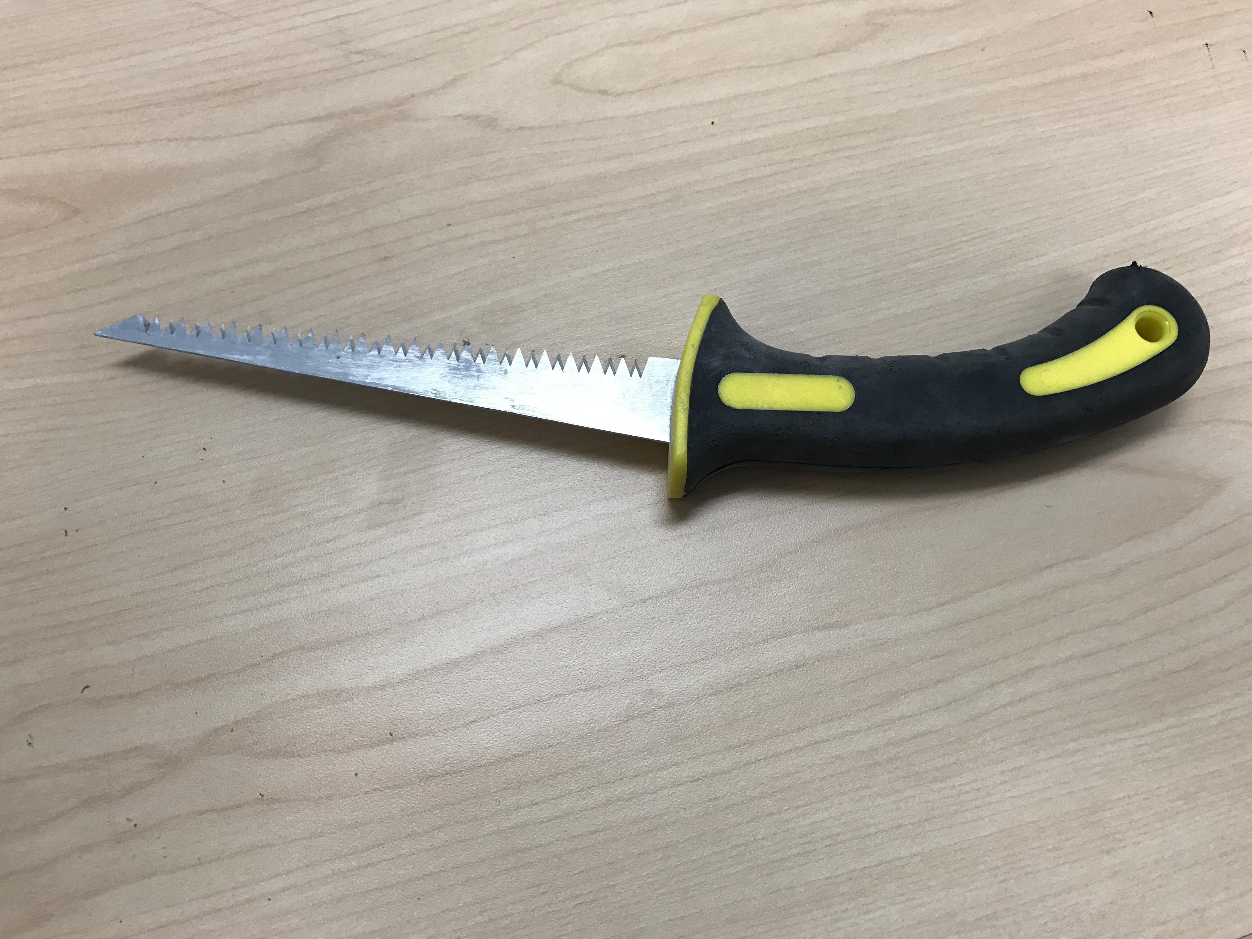
| + | * DryWall Saw | ||
| + | :{{img | file = DryWall_Saw.JPG | width=80px}} | ||
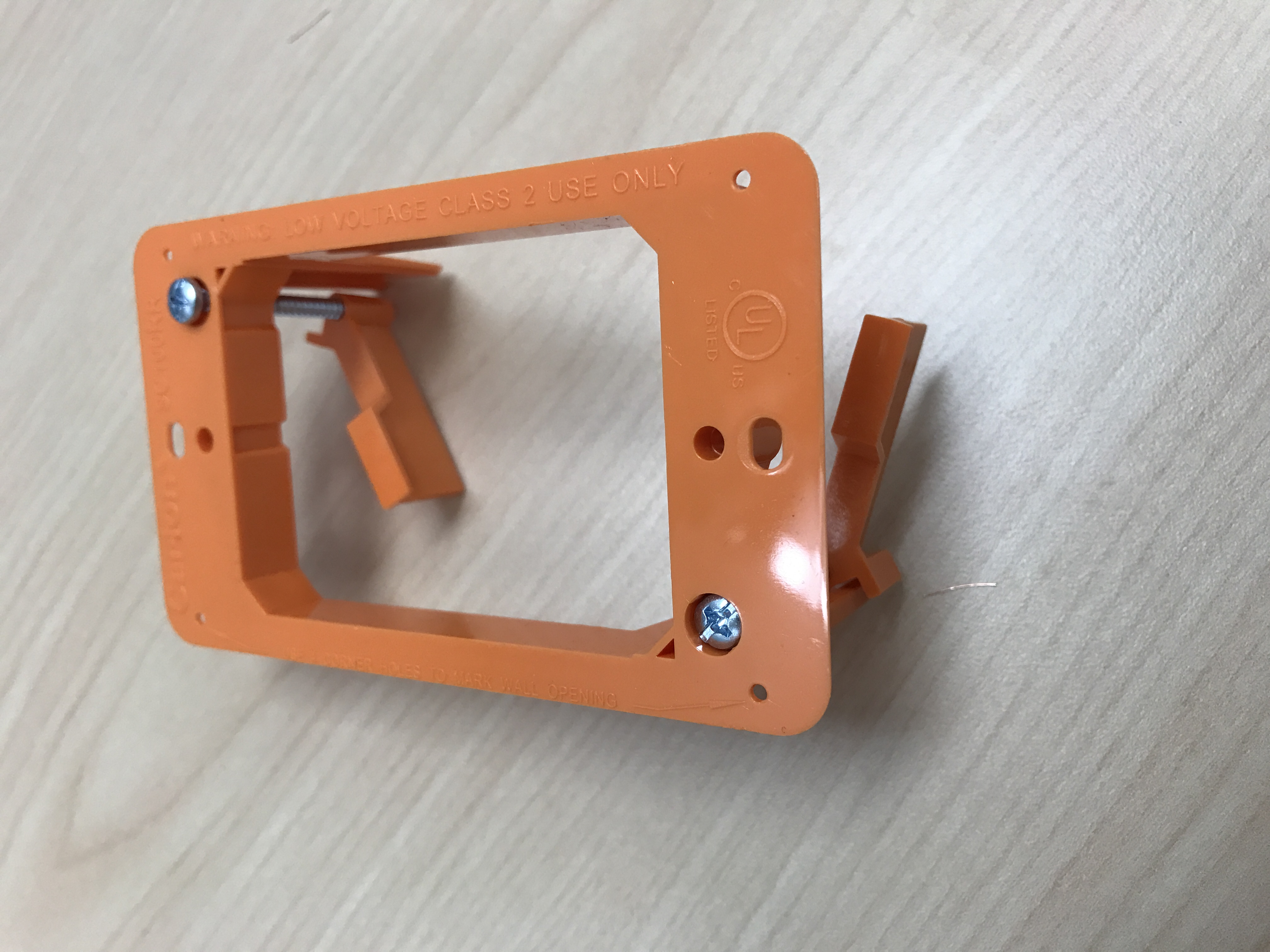
| + | * Mud Ring | ||
| + | :{{img | file = Mud_Ring.JPG | width=80px}} | ||
| + | * Electrical Tape | ||
==Installation Instructions== | ==Installation Instructions== | ||
| − | # | + | #Determine where the Securitron Tubular Key Switch to be located. Using a stud finder, determine that there aren't any studs behind the wall. |
| − | # | + | #Using a drywall saw, cut a rectangle in the drywall large enough to fit the mud ring into securely. |
| − | #: | + | #Using glow rods or fish tape, fish the 22/4 cable up and through the wall and ceiling the location of the camera is reached. |
| + | #Strip the jacket off of both ends of the cable revealing the 4 individual strands of cable. Strip those individual cables revealing their solid copper inside. | ||
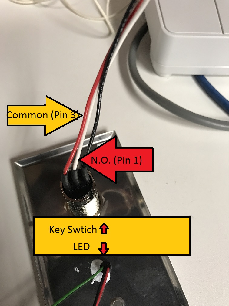
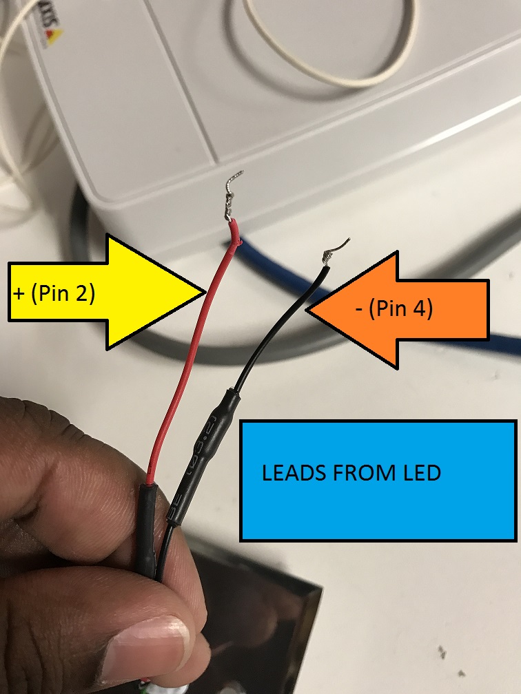
| + | #Open the Secuitron KeySwitch and strip the red and white leads from the tubular key portion revealing the stranded silver cable, and strip the back and red leads coming from the LED revealing the stranded silver cable. | ||
| + | #:{{img | file = KeySwitch Wires.JPG | width=300px}} {{img | file = LED WIRES Labeled.JPG | width=300px}} | ||
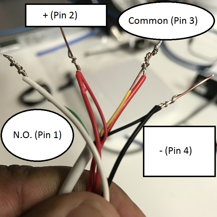
| + | #Wind the silver stranded cable around the solid copper of the 22/4 following the picture below. When wired, secure these connections with B-Connectors. | ||
| + | #:{{img | file = Switch All Wired.JPG | width=300px}} | ||
| + | #Once B-Connectors are secure, use the electrical tape to secure these wires together and place the excess into the wall. Screw the Securitron Key Switch into the mud ring mounting it flush to the wall. | ||
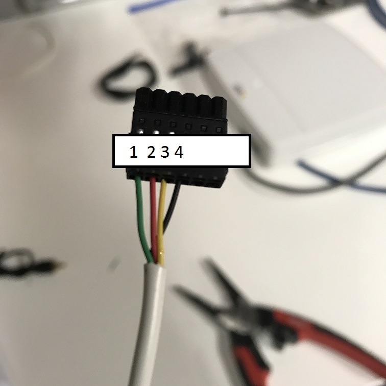
| + | #On the other end, connect the 22/4 exposed copper securely into the I/O Phoenix connector. Ensure that the wiring on is consistent from the keys switch (See Picture Below). | ||
| + | #:{{img | file = Wired_IO_Connector.JPG | width=300px}} | ||
Latest revision as of 14:02, 11 May 2022
Required Parts And Tools
- Securitron KP-1
- Wire Stripper
- Small Flat head screwdriver
- B Connectors
- Stud Finder
- 22/4 Solid Gauge Wire
- Fish Tape or Glow Rod
- DryWall Saw
- Mud Ring
- Electrical Tape
Installation Instructions
- Determine where the Securitron Tubular Key Switch to be located. Using a stud finder, determine that there aren't any studs behind the wall.
- Using a drywall saw, cut a rectangle in the drywall large enough to fit the mud ring into securely.
- Using glow rods or fish tape, fish the 22/4 cable up and through the wall and ceiling the location of the camera is reached.
- Strip the jacket off of both ends of the cable revealing the 4 individual strands of cable. Strip those individual cables revealing their solid copper inside.
- Open the Secuitron KeySwitch and strip the red and white leads from the tubular key portion revealing the stranded silver cable, and strip the back and red leads coming from the LED revealing the stranded silver cable.
- Wind the silver stranded cable around the solid copper of the 22/4 following the picture below. When wired, secure these connections with B-Connectors.
- Once B-Connectors are secure, use the electrical tape to secure these wires together and place the excess into the wall. Screw the Securitron Key Switch into the mud ring mounting it flush to the wall.
- On the other end, connect the 22/4 exposed copper securely into the I/O Phoenix connector. Ensure that the wiring on is consistent from the keys switch (See Picture Below).