Control Room Audio Solution
Contents
Description/Objective
In this example, we will be building 1 sim rooms with an overhead speaker and 1 observation room with live audio and a talkback microphone. For physical devices, there will be 1 room microphone, 1 camera, 1 OWISP, and 1 PSP speaker (and/or SHM-1 headphone amp).
Physical Wiring/Line Diagram
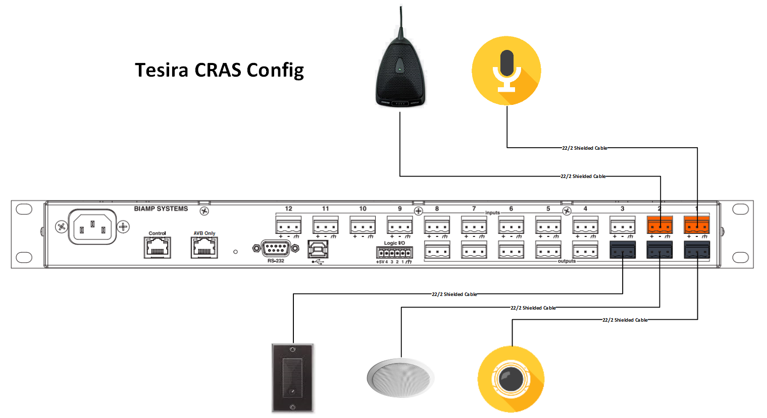
2 inputs and 3 outputs will be needed. The inputs and outputs should be as follows:
- Input 1: Sim Room Mic
- Input 2: Control Room Talkback Mic
- Output 1: Camera in Sim Room
- Output 2: OWISP in Sim Room
- Output 3: Control Room Speaker/HP Amp
Tesira Software
Connections
- If the physical connections are complete, open the Tesira software and start building a configuration.
- In this configuration use the following blocks:
- TesiraFORTE CI block ("per channel" AEC reference mode)
- Peak Meter x 3
- Uber Filter x 2
- Level Block
- Compressor with 2 channels, "ganged mode" and "advanced curve"
- Matrix Mixer with at least 2 inputs and 3 outputs, with 2 extra outputs
- Connect the blocks as follows:
- The Tesira Input block will already be connected to the AEC block, so connect the first peak meter to the Input block also. This will help ensure proper levels are set on the preamp.
- Connect the AEC block to the Uber Filters.
- Send the Uber Filters to the Level Block.
- Send the Level Block to the Compressor and the second peak meter.
- Send the Compressor to the Matrix Mixer.
- Connect output 1-3 from the mixer to port 1-3 on the Tesira Output block AND to the third peak meter. This will ensure the right audio levels are sent to the camera.
- Connect the 2 extra outputs from the Matrix Mixer to ports 1&2 on the AEC reference.
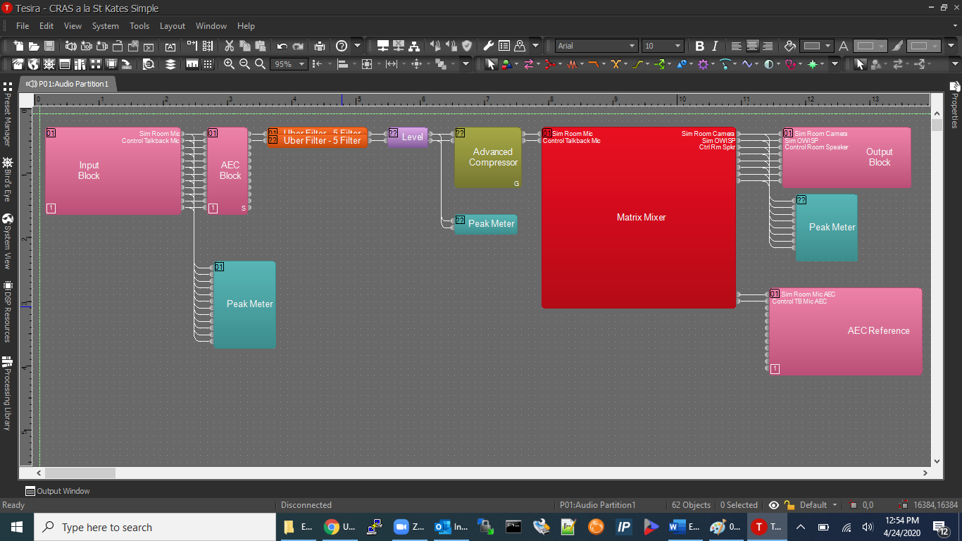
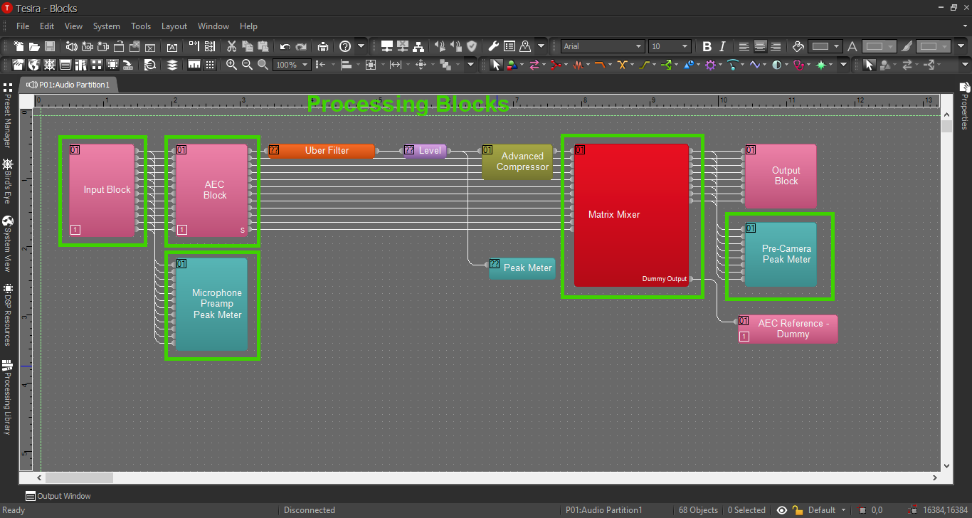
When this is complete, the file should look something like this:
AEC Block
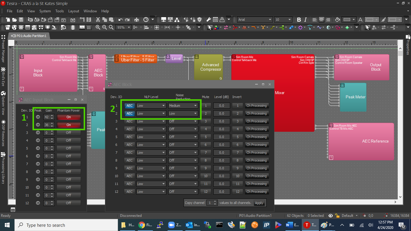
- Phantom Power: The mics will need phantom power, and proper levels on the preamps. Use the peak meter to gauge the audio levels so that optimal dialog peaks between -12 and 6 dB.
- AEC: For the first time in the example configurations, Acoustic Echo Cancellation will be used. The reason for this is: anytime there is a microphone and a talkback speaker in the same room, there is the opportunity for an echo and/or feedback. AEC will cancel the delayed audio or feedback. Enable the AEC feature with this button on the AEC Block. AEC is explored in depth in another section.
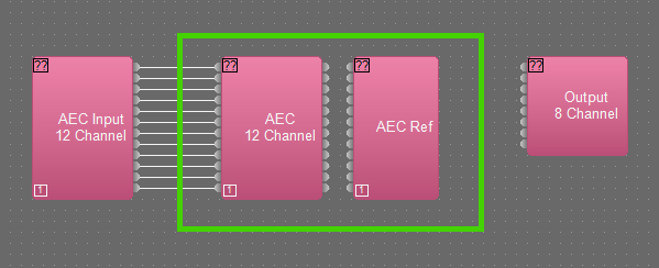
Acoustic Echo Cancellation
AEC is important, and sometimes difficult to understand. There is a separate section on how to configure AEC. Click the image below to read up on AEC:
Processing Blocks in Tesira
For further insight about the other processing blocks and settings, refer back to the first configuration example, or click the image below:
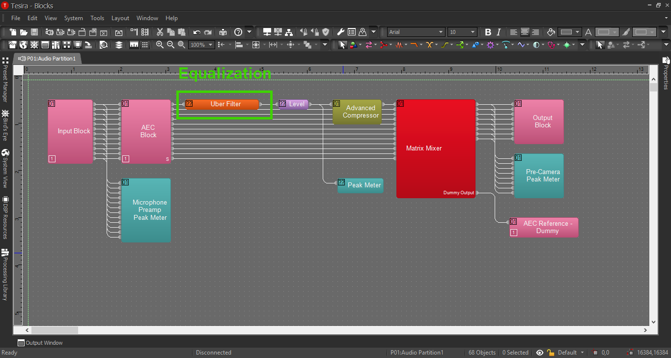
EQ and Compression
For information on EQ settings, or click the image below:
For Compression parameters, click the image below:
