Infrared (IR) Talkback
Required Parts and Tools
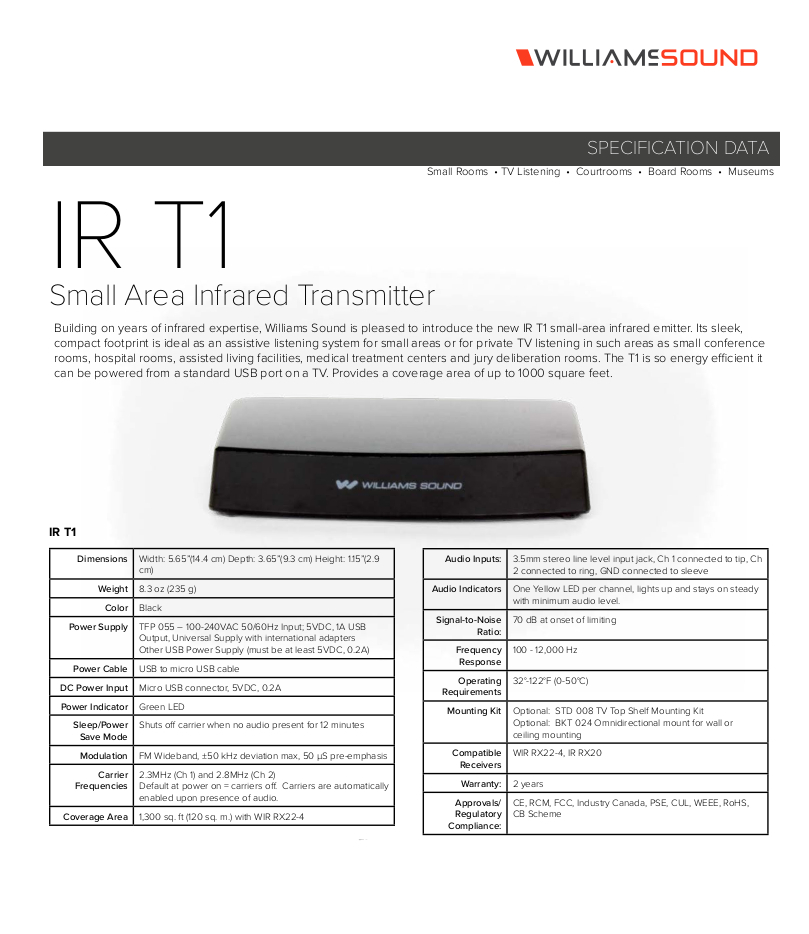
- Williams Talkback System IR T1
- Williams RX224 Receiver
- PanaVise Deluxe CCTV Camera Mount
- 22/2 audio cable
- B Connectors
- Fish Tape or Glow Rods
- Wire Stripper
Installation Instructions
Connecting to the Camera
- Once the camera is installed, locate the AUDIO OUT on your camera
- Connect 22/2 wire, red to positive and black to the ground of the AUDIO OUT
IR Device mounting Instructions
- Determine the placement of the IR receiver. It will generally be best suited to be positioned in a corner.
- Remove the drop ceiling tile to which the IR receiver will be mounted
- Note: The IR receiver will be mounted as far back to the corner as space allows
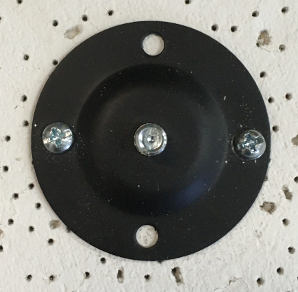
- Remove the mounting hardware from its packaging (necessary mounting hardware shown below)
- Using toggle bolts, secure the mounting plate to the drop ceiling
- Note: If encountering hard ceiling, use anchors and screws (3/16")
- Drill a small hole behind where the IR transmitter will be mounted for passing cables through
- Run the 22/2 cable connected to the AUDIO OUT to the IR T1.
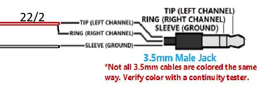
- Splice a 3.5mm audio cable with the 22/2 using B-connectors. Red on the 22/2 to the red and L/R on the 3.5mm. Black on the 22/2 to the bare of the 3.5mm.


- Attach mount arm the IR reciever
- Place the mount cover over the plate and twist the mounting arm until secure
- Plug the 3.5 cable into the Line In of the IR T1 and connect the power cable
- Return the ceiling tile to it's appropriate location
- Once audio is plugged in, locate your nearest power outlet to power the IR T1.


- Note: It is preferred that there is a standard power outlet above the ceiling, otherwise you will run the USB Type A to B down the wall to the nearest outlet.
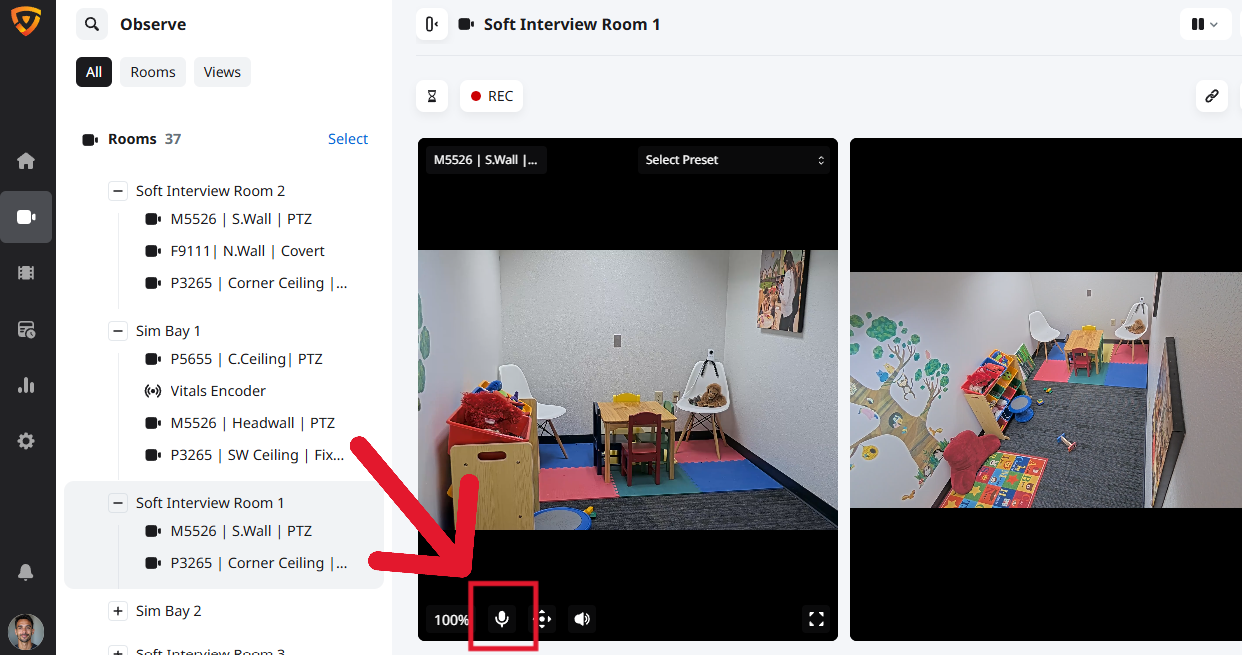
Testing the System
- Ensure your IR T1 and reciever are set to the same channel.
- Test the talkback unit is working by activating the talkback function within the VALT Software and having a partner to communicate with.