Installing an Axis P3245 with a Shure MX202i Microphone
Contents
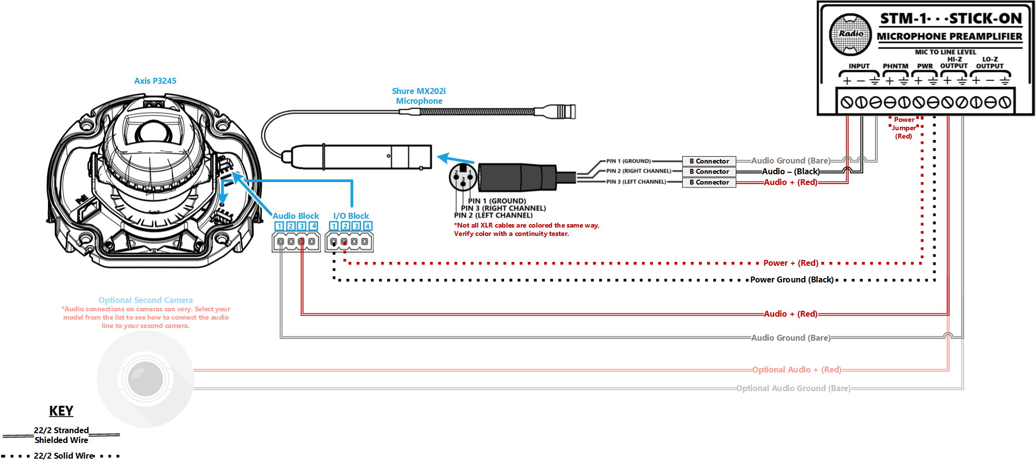
Wiring Diagram
Select Optional Second Camera
![]() Axis P3235
Axis P3235
![]() Axis P3245
Axis P3245
![]() Axis P3364/P3365
Axis P3364/P3365
![]() Axis P3374/P3375
Axis P3374/P3375
![]() Axis Axis F41
Axis Axis F41
![]() Axis P5414/P5415
Axis P5414/P5415
![]() Axis Axis M5525
Axis Axis M5525
![]() Axis Axis P5635
Axis Axis P5635
![]() Axis P5655
Axis P5655
![]() Axis V5914/V5915
Axis V5914/V5915
![]() Axis Q8414
Axis Q8414
Required Parts And Tools
- Axis P3245-LV
- RDL STM-1
- Female XLR Pigtail
- Shure MX202i Microphone
- T20 Torx security bit
- T10 Torx security bit
- Wire Stripper
- Tap-Cons (if mounting to concrete) (7/8")
- Screws and Anchors (7/8")
- 1/2" paddle bit
- 1 blank single gang wall plate
- Toggle Bolts (for mic mount) (3/16")
- Drill bit and drill
- Phillips head drill bit or Phillips head screwdriver
- Small Flat head screwdriver (#3)
- Hole Saw (2")
- B Connectors
- Stud Finder
- Cat5/6 Patch Cable (7ft-15ft recommended)
- Shielded Stranded 22/2 + ground Wire
- Fish Tape or Glow Rods
- Wind Screen (Inside MX202i kit)
- Rubber Stopper (Inside MX202i kit)
- 4 pin XLR-M to XLR-M Adapter (Inside MX202i kit)
Installation Instructions
Disassemble the Camera
- Locate the network drop above the ceiling. It should be terminated with a male Ethernet end (service loop) or a biscuit jack. This line will have been ran back to the POE switch.
- Note: If the switch does not have POE, a POE injector will need to be installed at the network closet.
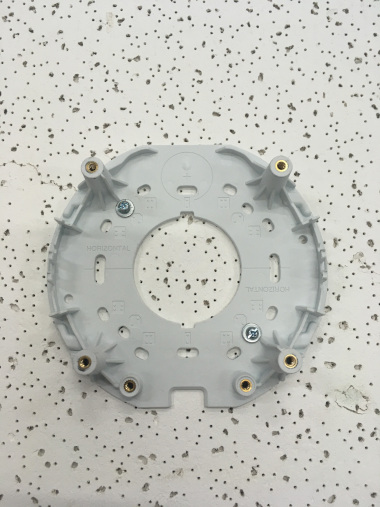
- Using the T20 bit, remove the dome from the 3245.
- Remove the camera from the mounting plate.
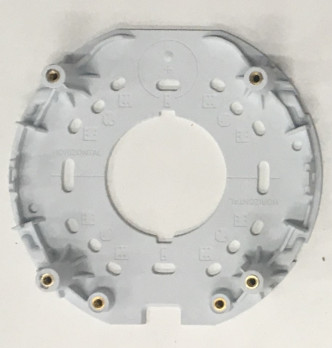
Mount the Camera
Drywall mounting instructions
- Using a stud finder, scan the mount location to ensure the camera is not mounted on a stud.
- Using a pencil, mark the four holes for the mount plate.
- Using a 3/16" drill bit, drill the marked locations and
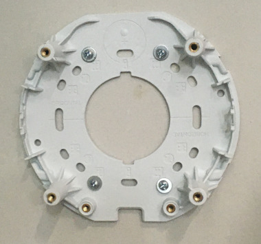
- Install anchors and attach the mount plate using screws and washers.
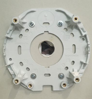
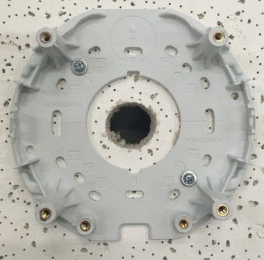
- Using a hole saw or paddle bit, cut a hole centered in the wall plate where cables will pass through.
- Using the hole saw, drill a hole above the drop ceiling in line with the hole drilled where the camera is mounted.
- Cut two lengths of 22/2 long enough to reach the mounting location of the microphone.
- Using glow rods or fish tape, fish the network drop or patch cable in addition to the two sections of 22/2 audio cable through the drywall.
- Attach the camera the the mount plate
Drop Ceiling mount instructions
- If mounting to drop ceiling, determine where the camera will be located on the tile. Ensure that there will be clearance on the tile to secure the dome in place.
- Using two toggle bolts, secure the mount plate.
- Using a 1" paddle bit, drill a hole centered in the opening of wall plate. This is where cables will pass through.
- Cut two lengths of 22/2 long enough to reach the mounting location of the microphone.
- Using glow rods or fish tape, fish the network drop and 2 sections of 22/2 audio cable into the drop ceiling.
- Attach camera to mount plate.
-
Note: Be careful not to press too hard and damage the ceiling tile
Connect Wiring
- Connect patch cable into the Ethernet port on the Axis P3245.
- Note: When connected, activity will be visible on the link lights. If no link lights appear, ensure that POE is enabled on the POE switch and that the network drop is plugged in. After approximately one minute, all three LEDs should be green.
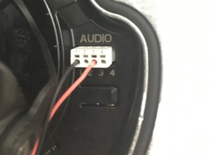
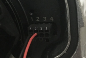
- At the camera, connect the power cable to the I/O phoenix connector (Red to 2, Black to 1). Connect the audio cable to the audio terminal block (Red to 3, Black to 1)
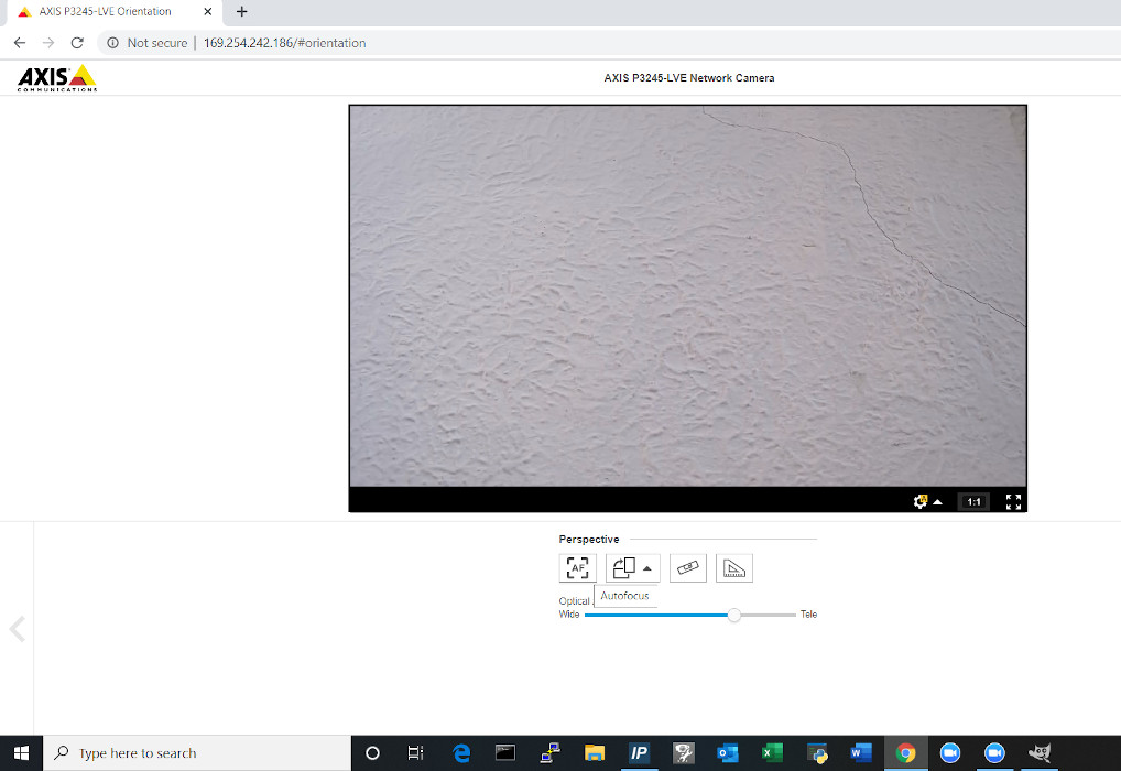
Aim the Camera
- In order to aim the camera, it will need to be accessed via the Axis web portal.
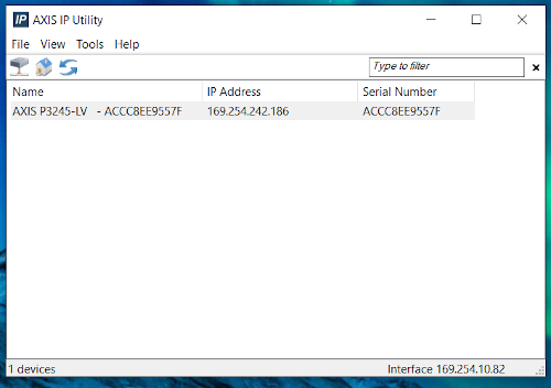
- If the camera is being powered off the network, run Axis IP utility in order to discover the camera. Clicking the IP address will route to the Axis web portal
-
- If that does not work then use a POE injector to connect to the camera and the default IP. (default Axis IP = 192.168.0.90)
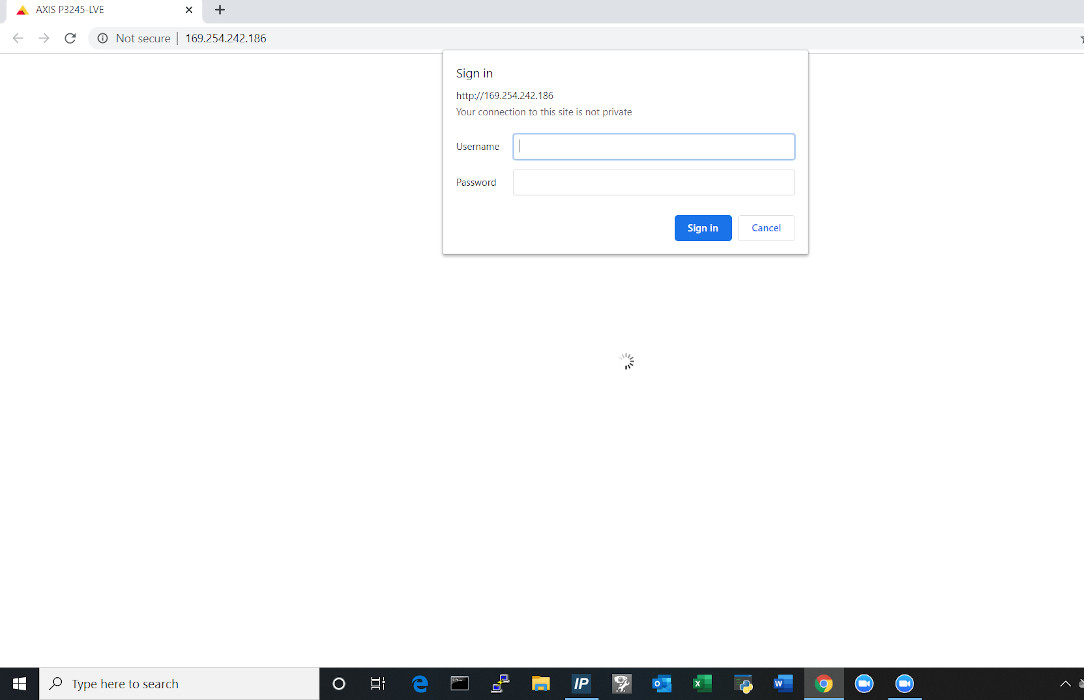
- Using a laptop/PC, enter the IP address assigned to the camera into a web browser.
- Using the IVS admin credentials, log into the camera.
- User: root
- Password: admin51
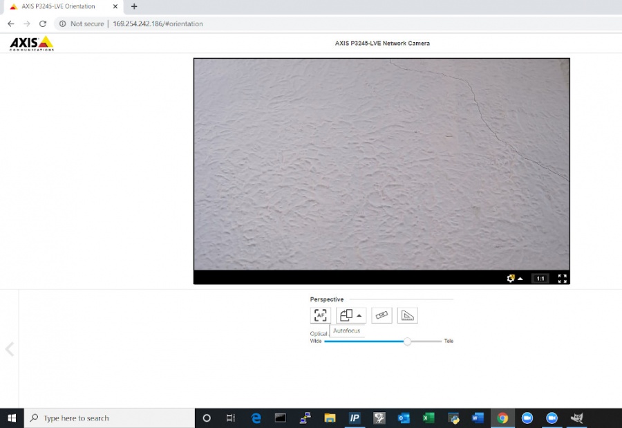
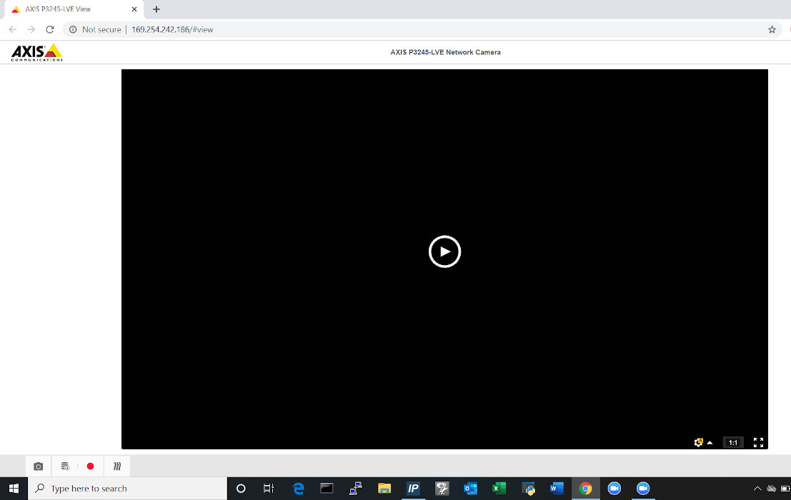
- Once in the Axis web portal, activate the camera live view.
-
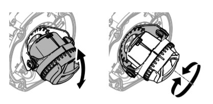
- Begin by manually adjusting camera's viewing area using the manual tilt and focus mechanisms on the camera.
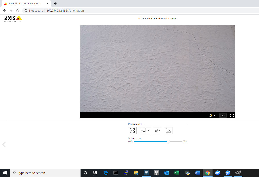
-
- Using the digital zoom function in the web portal, make any other adjustments needed.
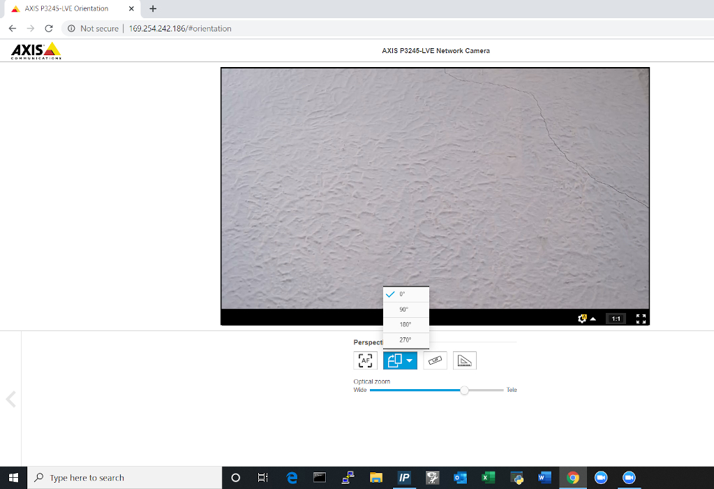
- The image field may also be rotated in the web portal if necessary.
-
- Be sure to click the Autofocus button. This will focus the camera and ensure that the autofocus is properly functioning.
-
- Note: This must be done before securing the dome.
-
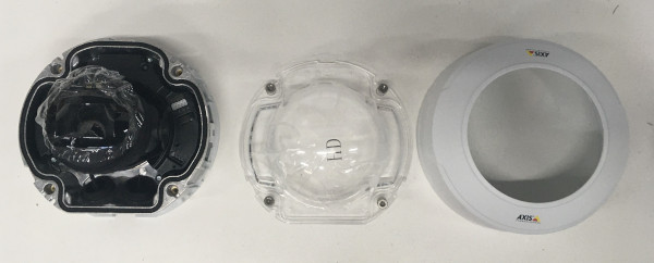
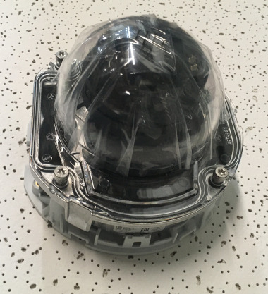
Reassemble the Camera
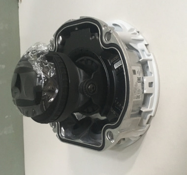
- Remove protective film before securing dome
- Place the dome over on the camera. Using the T20 bit, tighten the dome cover in place.
- Snap the Axis dome ring into the base plate
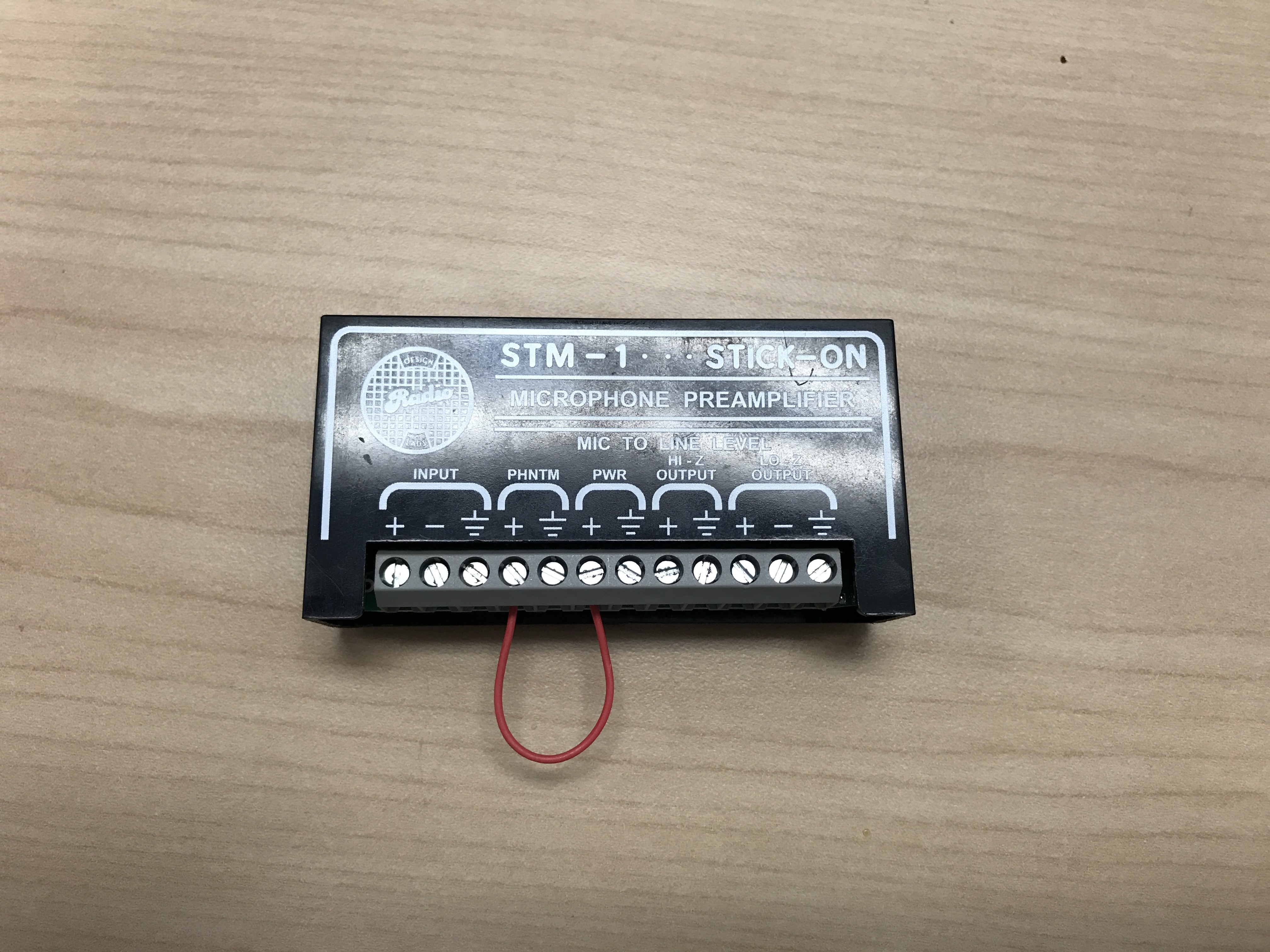
Connecting the STM-1
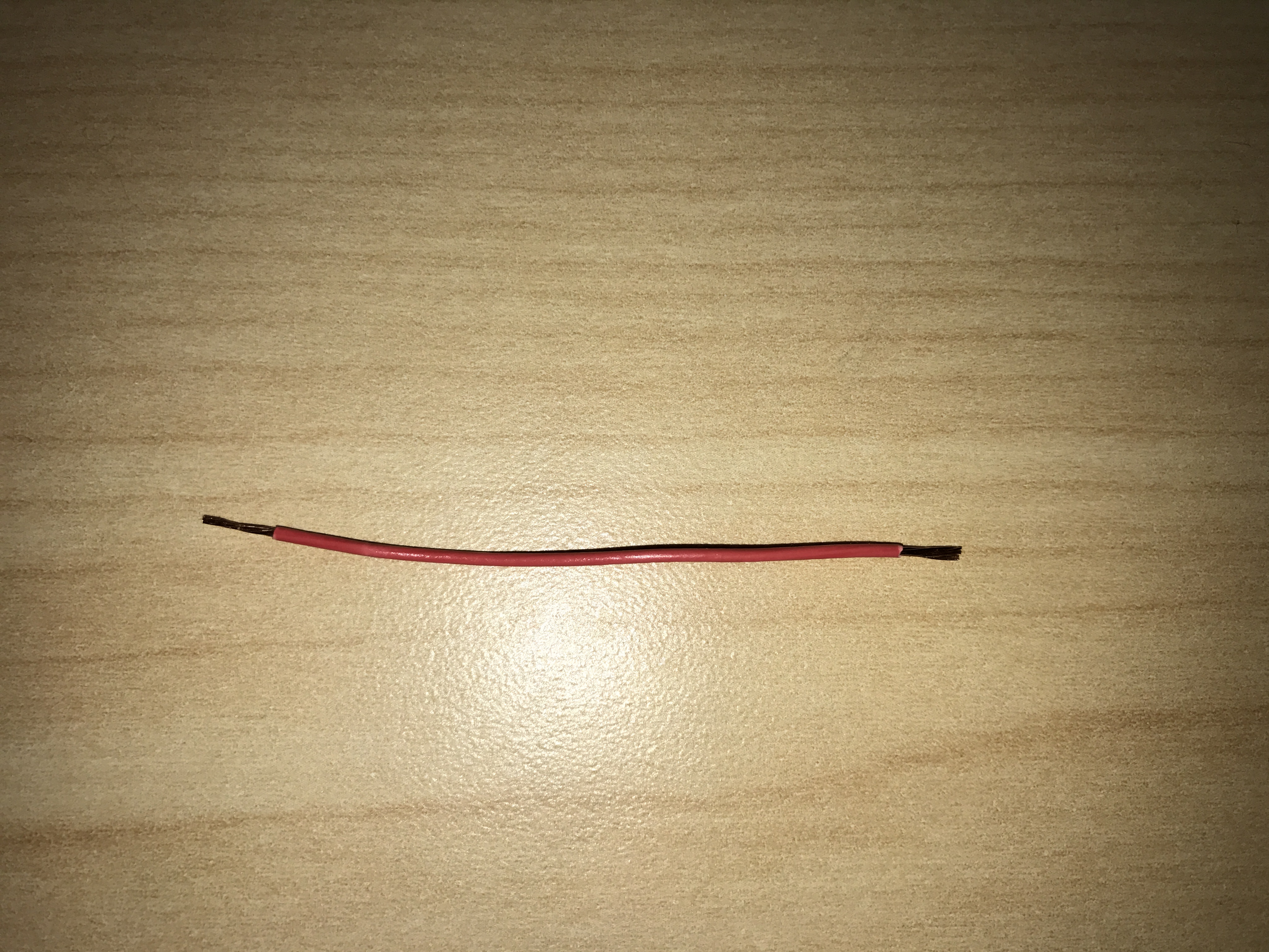
- Cut a short piece of 22/2 cable (approx. 1 inch). Strip the jacket and from the cable and remove all contents keeping only the red cable. On both ends of the red cable, strip off a piece of the jacket (See picture).
-
- Connect one end of the 1 inch audio cable to the +PWR terminal and connect the other end into the +PHNTM terminal.
-
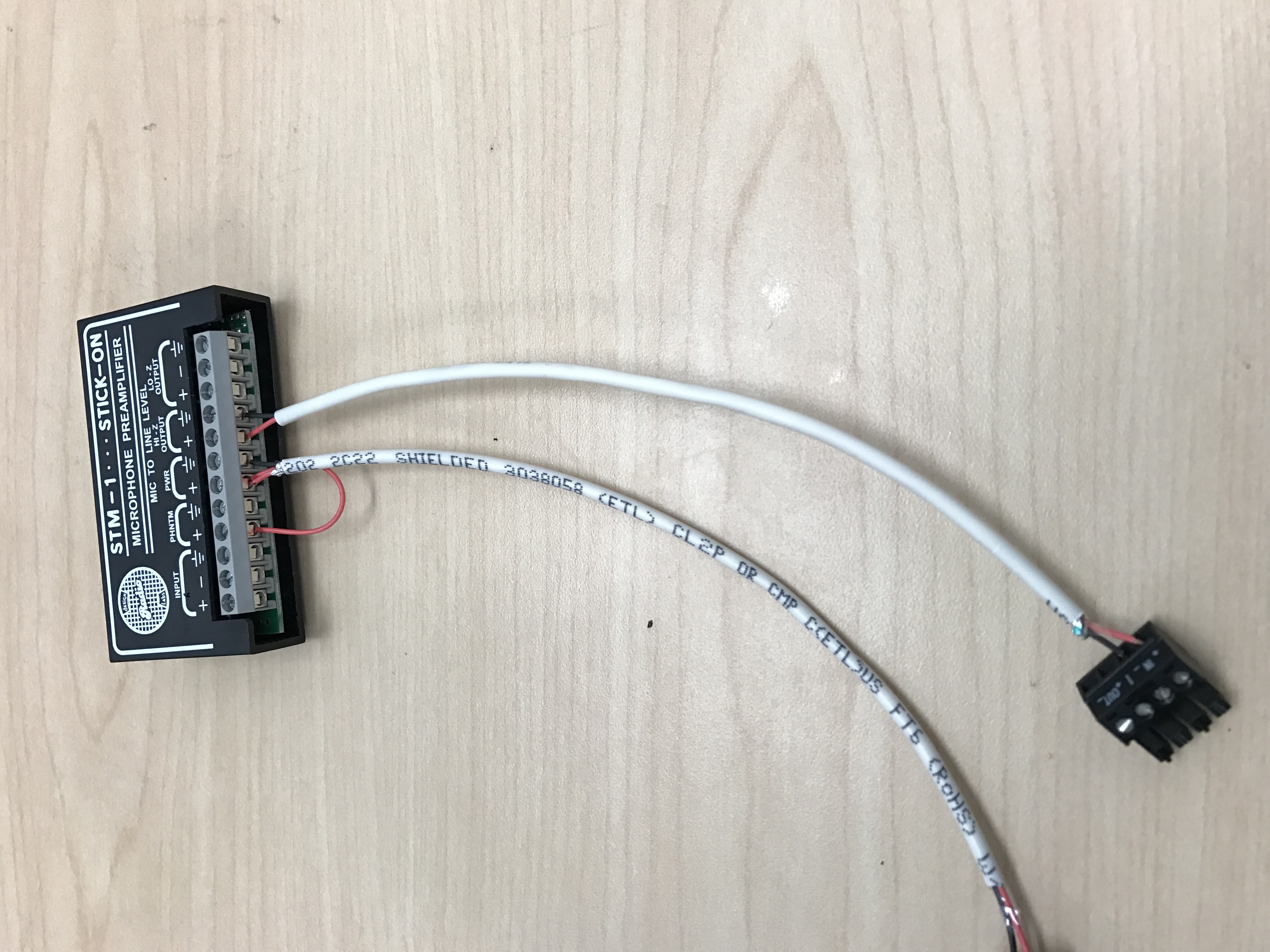
- Connect the cable ran for power to both PWR terminals (Red to +, Black to the other terminal) of the STM-1. Connect the other side to the IO phoenix connector (Red to 2, Black to 1).
- Connect the cable ran for audio to both HI-Z OUTPUT terminals (Red to +, Black to the other terminal) of the STM-1. Connect the other side to the audio in portion of the audio phoenix connector (Red to +, Black to –).
-
- Using the Velcro that comes with the STM-1, attach the STM-1 to the wall above drop ceiling hidden from sight.
- The microphone will be connected via the input terminals of the STM-1 (Red to +, Black to -, ground to the ground terminal).
(NOTE: If there are 2 cameras in the room, duplicate these steps to get to the 2nd camera. HI-Z output can feed 2 cameras, but no more. If there are 2 Shure MX202i Microphones, duplicate steps. An STM-1 can power and gather audio from 2 Shure 202i mics.)
Connecting and Mounting the Microphone
- Asses the drop ceiling to decide best mounting placement for the MX202i. Avoid tiles adjacent to HVAC or fire safety devices.
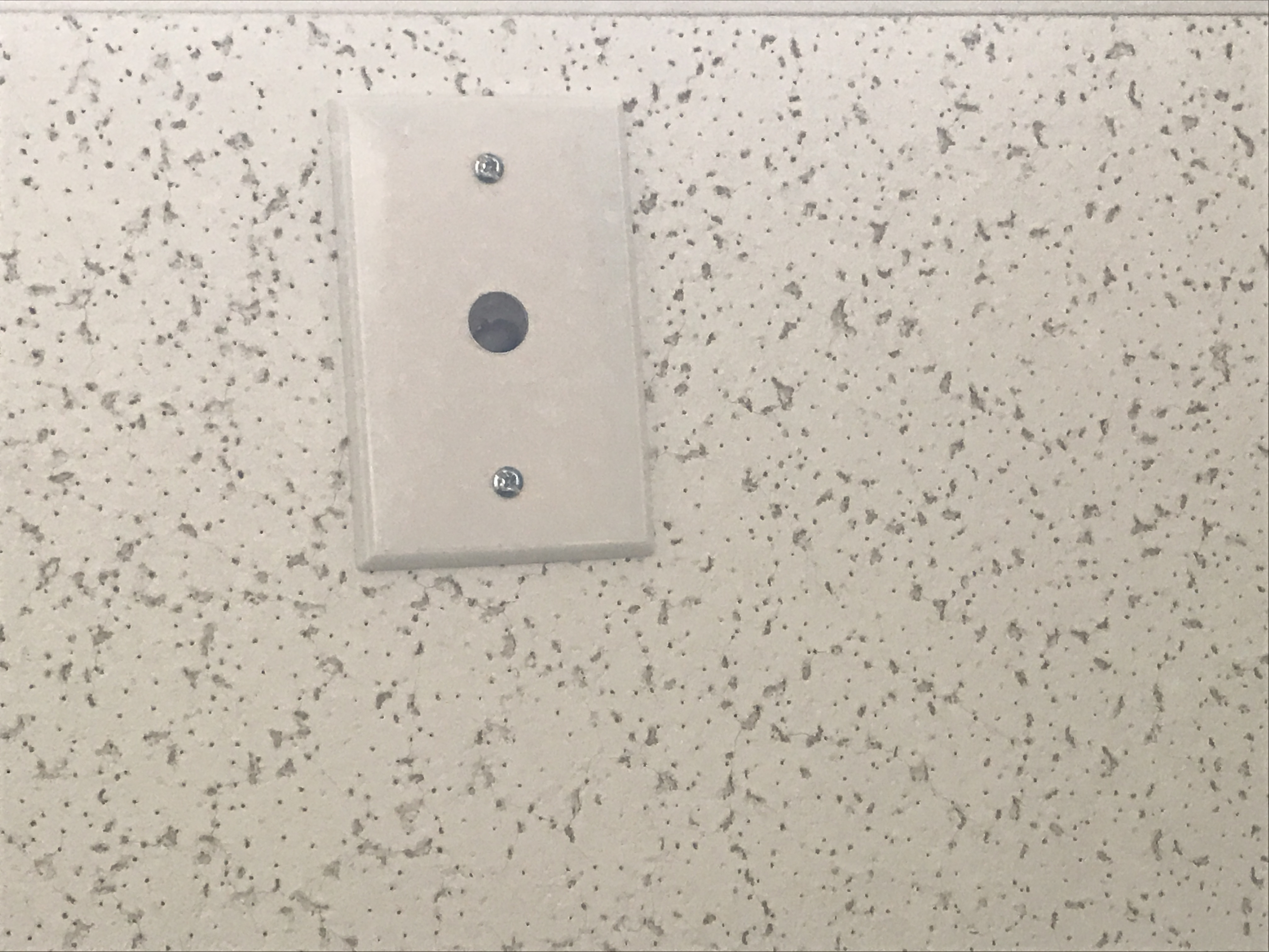
- Drill a hole into the center of the single gang plate using the ½” paddle bit (if not prefabricated).
- Measure center of the drop ceiling tile and drill a similar hole with the ½” paddle bit.
- Align the single gang plate to the location of the microphone on the drop ceiling tile using a pair of toggle bolts.
-
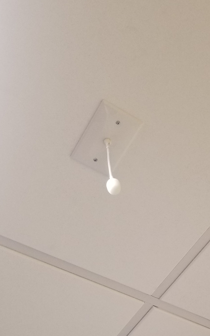
- Run the MX202i through the ½” hole in the ceiling tile and single gang plate with the rubber stopper to secure the microphone in place and plugging the ½” hole .
- Adjust the length of the cable of the microphone to a desirable length, hiding the remainder in the ceiling near the STM-1. Attach the windscreen to the MX202i.
-
- Run the XLR mini cable to the STM-1 location.
- Connect the connect the XLR mini to the 4 pin Male XLR adapter.
- Strip away a portion of the red and black cables inside the pigtail, revealing the copper wire inside.
- The microphone will be connected via the input terminals of the STM-1 (Red to +, Black to -, ground to the ground terminal).
- Connect the female XLR to the Male XLR adapter