Installing an Axis P3364/P3365 with a Louroe Verifact A Microphone
Contents
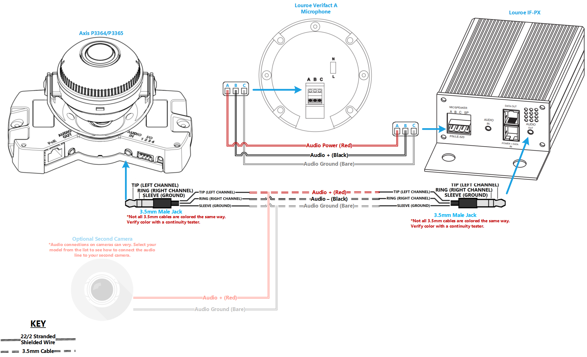
Wiring Diagram
Select Optional Second Camera
![]() Axis P3235
Axis P3235
![]() Axis P3245
Axis P3245
![]() Axis P3364/P3365
Axis P3364/P3365
![]() Axis P3374/P3375
Axis P3374/P3375
![]() Axis Axis F41
Axis Axis F41
![]() Axis P5414/P5415
Axis P5414/P5415
![]() Axis Axis M5525
Axis Axis M5525
![]() Axis Axis P5635
Axis Axis P5635
![]() Axis P5655
Axis P5655
![]() Axis V5914/V5915
Axis V5914/V5915
![]() Axis Q8414
Axis Q8414
Required Parts And Tools
- Axis P3364 or P3365
- Louroe IFPX
- 3.5mm (Male to Male) Audio Cable
- Louroe Verifact A Microphone
- S2 TT20 Torx security bit
- Wire Stripper
- Tapcons (if mounting to concrete) (3/16")
- Screws and Anchors (3/16")
- Toggle Bolts (If mounting to drop ceiling tile) (3/16")
- Drill bit and drill
- Phillips head drill bit or Phillips head screwdriver
- Small Flat head screwdriver (#3)
- Cat5/6 Patch Cable (7ft-15ft recommended)
- Shielded Stranded 22/2 + ground Wire
Installation Instructions
Disassemble the Camera
- Locate the network drop above the ceiling. It should be terminated with a male Ethernet end (service loop) or a biscuit jack. This line will have been ran back to the POE switch.
- Note: If the switch does not have POE, a POE injector will need to be installed at the network closet.
- Using the T20 bit, remove the dome from the 3364/65.
Mounting the IFPX
- Using a set of wall dog screws, mount the Louroe IFPX above into the drywall above drop ceiling.
- Note: If no drop ceiling make other arrangements to mount the IFPX.
- Connect the network drop into the RJ-45 (f) on the IFPX that reads Power+Data In. When connected, activity will be seen on the link lights. If no link lights, ensure that POE is enabled on the POE switch and that the network drop is plugged in.
Drywall Mounting instructions
- Determine mounting height and location
- Using a stud finder, ensure there aren’t any studs any behind the camera base.
- Using a pencil, mark the two holes where the camera base well be attached
- Mark another location to run cabling behind the drywall
- Drill the marked locations
- Using the hole saw, drill a hole above the drop ceiling in line with the hole drilled where the camera will be mounted.
- Insert anchors
- Using glow rods or fish tape, run the 22/2, 3.5mm, and network cable behind drywall
- Mount the camera using screws
Drop Ceiling Inscructions
- Remove the ceiling tile the camera will be mounted to and determine where on the tile to mount.
- Using a pencil, mark the two holes where the camera base well be attached
- Make a small hole that can be hidden by the camera dome for running cabling through.
- Using toggle bolts, mount the camera.
- Return ceiling tile with mounted camera to drop ceiling.
- Run 22/2, 3.5 mm, and network cable to IFPX location
Connecting the IFPX
- Using the CAT5/6 patch cable, connect the camera to the RJ-45 (f) on the IFPX, labeled Power+Data Out. When connected, you should see the NET, STATUS, and POWER LEDs light up on the camera. After approximately 1 minute, all 3 should be green. If not, check connections.
- Take the 3.5mm Male to Male audio cable and connect it from the 3.5mm jack labeled AUDIO OUT on the IFPX, into the pink AUDIO IN on the P3364 or P3365 camera. (See Picture)

Connecting the Microphone
- Strip the jacket off the 22/2, revealing the red, black, and common (bare wire) on both sides of the cable. Remove the string and plastic casings covering the red and black cables. Strip the red and black jackets off the wire exposing the copper. Cut copper evenly on both ends (See picture)
- Drill a hole into the piece of ceiling tile that you will be mounting the Louroe Verifact-A. Feed one end of the the 22/2 audio cable through the hole. Connect the audio cable to the Verifact-A phoenix terminal as follows; Red to A, Black to B, Common (bare wire) to C (See Picture)
- Connect the other end of your 22/2 cable to the terminal on the IFPX labeled MIC/SPEAKER A B C SP. The connections will be as follows; Red to A, Black to B, Common (bare wire) to C (See Picture)
- Place the dome over on the camera. Using the T20 bit, tighten the dome cover in place.


