Installing an Axis P3364/P3365 with a Shure MX202i Microphone
Contents
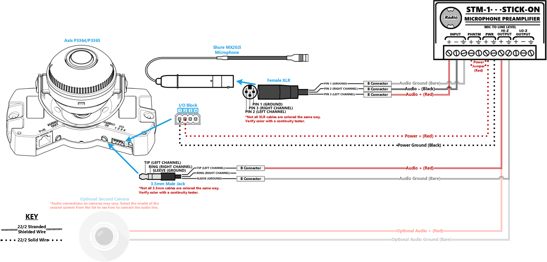
Wiring Diagram
Select Optional Second Camera
![]() Axis P3235
Axis P3235
![]() Axis P3245
Axis P3245
![]() Axis P3364/P3365
Axis P3364/P3365
![]() Axis P3374/P3375
Axis P3374/P3375
![]() Axis Axis F41
Axis Axis F41
![]() Axis P5414/P5415
Axis P5414/P5415
![]() Axis Axis M5525
Axis Axis M5525
![]() Axis Axis P5635
Axis Axis P5635
![]() Axis P5655
Axis P5655
![]() Axis V5914/V5915
Axis V5914/V5915
![]() Axis Q8414
Axis Q8414
Required Parts And Tools
- Axis P3364 or P3365
- Louroe IFPX
- 3.5mm (Male to Male) Audio Cable
- Louroe Verifact A Microphone
- S2 TT20 Torx security bit
- Wire Stripper
- Tapcons (if mounting to concrete) (3/16")
- Screws and Anchors (3/16")
- Toggle Bolts (If mounting to drop ceiling tile) (3/16")
- Drill bit and drill
- Phillips head drill bit or Phillips head screwdriver
- Small Flat head screwdriver (#3)
- Cat5/6 Patch Cable (7ft-15ft recommended)
- Shielded Stranded 22/2 + ground Wire
- RDL STM-1
- Female XLR Pigtail
- Shure MX202i Microphone
- Fish Tape or Glow Rods
- Wind Screen (Inside MX202i kit)
- Rubber Stopper (Inside MX202i kit)
- 4 pin XLR-M to XLR-M Adapter (Inside MX202i kit)
Installation Instructions
Disassemble the Camera
- Locate the network drop above the ceiling. It should be terminated with a male Ethernet end (service loop) or a biscuit jack. This line will have been ran back to the POE switch.
- Note: If the switch does not have POE, a POE injector will need to be installed at the network closet.
- Using the T20 bit, remove the dome from the 3364/65.
Mounting the IFPX
- Using a set of wall dog screws, mount the Louroe IFPX above into the drywall above drop ceiling.
- Note: If no drop ceiling make other arrangements to mount the IFPX.
- Connect the network drop into the RJ-45 (f) on the IFPX that reads Power+Data In. When connected, activity will be seen on the link lights. If no link lights, ensure that POE is enabled on the POE switch and that the network drop is plugged in.
Drywall Mounting instructions
- Determine mounting height and location
- Using a stud finder, ensure there aren’t any studs any behind the camera base.
- Using a pencil, mark the two holes where the camera base well be attached
- Mark another location to run cabling behind the drywall
- Drill the marked locations
- Using the hole saw, drill a hole above the drop ceiling in line with the hole drilled where the camera will be mounted.
- Insert anchors
- Using glow rods or fish tape, run the 22/2, 3.5mm, and network cable behind drywall
- Mount the camera using screws
Drop Ceiling Inscructions
- Remove the ceiling tile the camera will be mounted to and determine where on the tile to mount.
- Using a pencil, mark the two holes where the camera base well be attached
- Make a small hole that can be hidden by the camera dome for running cabling through.
- Using toggle bolts, mount the camera.
- Return ceiling tile with mounted camera to drop ceiling.
- Run 22/2, 3.5 mm, and network cable to IFPX location
Connecting the IFPX
- Using the CAT5/6 patch cable, connect the camera to the RJ-45 (f) on the IFPX, labeled Power+Data Out. When connected, you should see the NET, STATUS, and POWER LEDs light up on the camera. After approximately 1 minute, all 3 should be green. If not, check connections.
- Take the 3.5mm Male to Male audio cable and connect it from the 3.5mm jack labeled AUDIO OUT on the IFPX, into the pink AUDIO IN on the P3364 or P3365 camera. (See Picture)

Connecting Wiring
- Strip the jacket off the 22/2, revealing the red, black, and common (bare wires) on both cables. Remove the string and plastic casings covering the red and black cables. Strip the red and black jackets off the wire exposing the copper. Cut copper evenly. On the cable we ran for power, remove the common (bare wire) completely.
- Cut a 3.5 mm audio cable in half. Strip about an inch of the black jacket; then strip about 1/2 inch of red and white strand jacket. Test the 3.5 cable for polarity (touch one end of the cable tester to the tip of the 3.5 jack and the other end to the red and white wires. This will be the positive wire; the middle section of the 3.5 jack is negative wire; the bottom section of the jack is ground/stranded wire.) Splice these wires with the camera end of the 22/2 cable we just ran for audio.
- Connect the power cable to the IO phoenix connector (Red to 2, Black to 1).
- Plug in the network drop to the PoE NIC, the 3.5 jack into the pink AUDIO IN port on the camera, and the IO phoenix connector to the IO port.
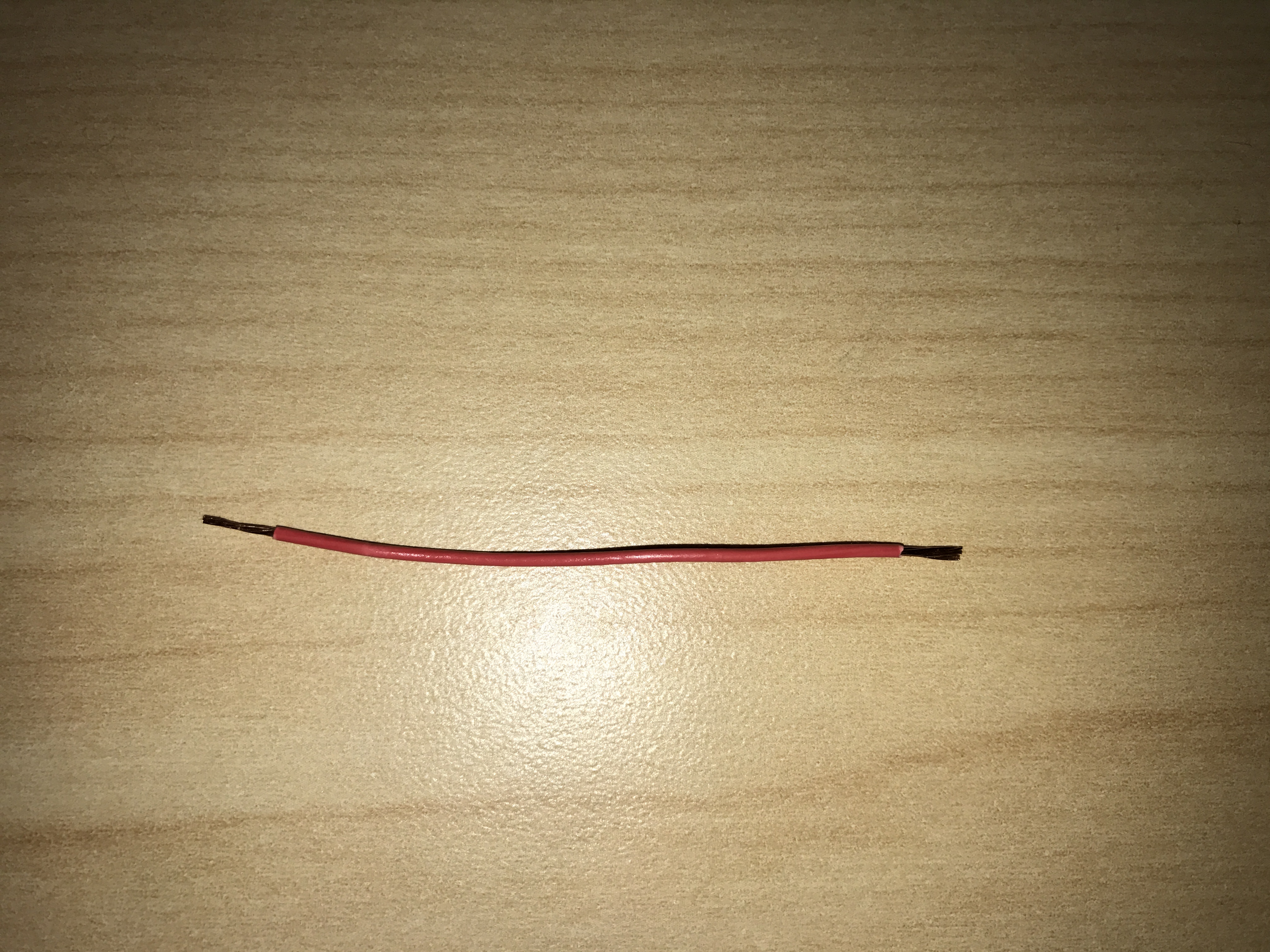
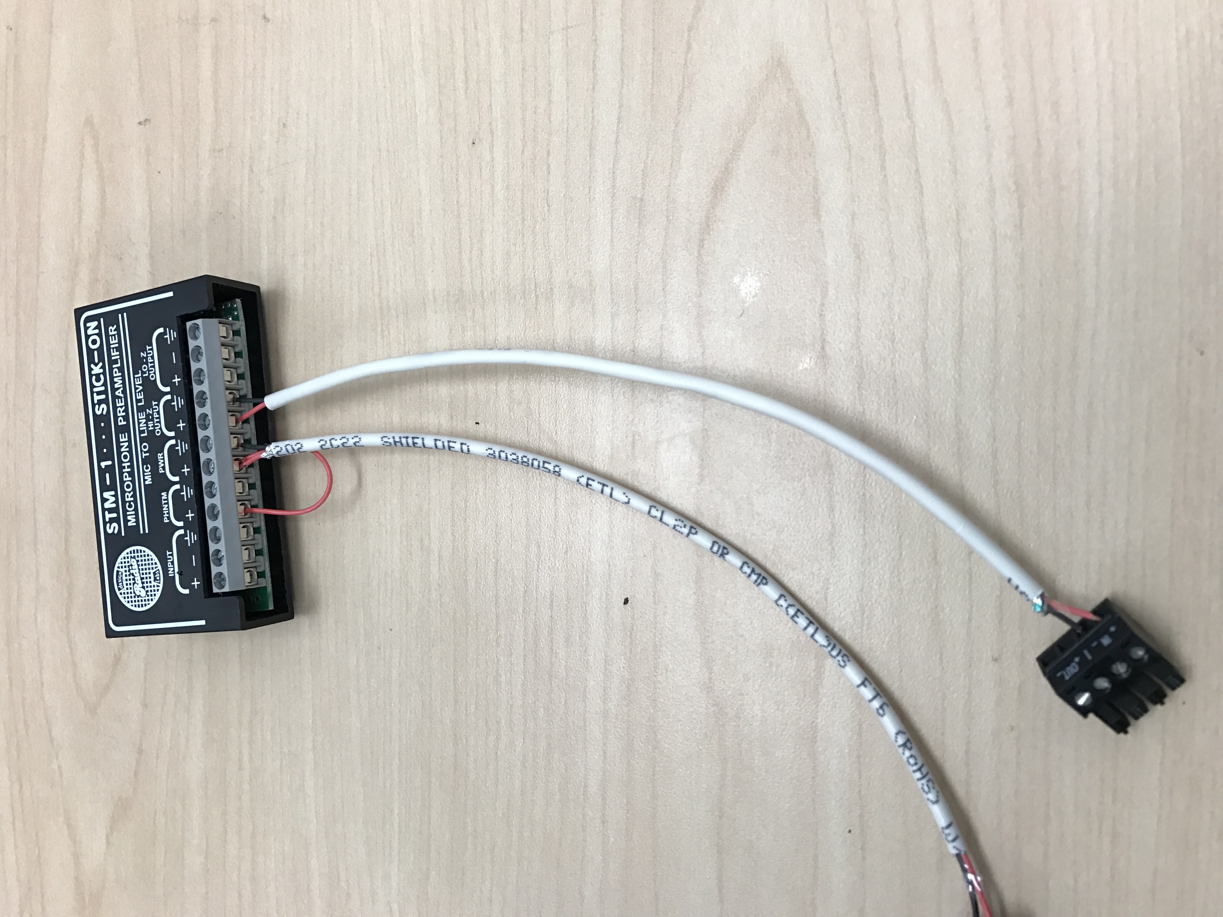
- You will also need to cut another shorter piece of 22/2 cable (approx. 1 inch). Strip the jacket from the cable and remove all contents keeping only the red cable. On both ends of the red cable, strip off a piece of the jacket (See picture).

Connecting the STM-1
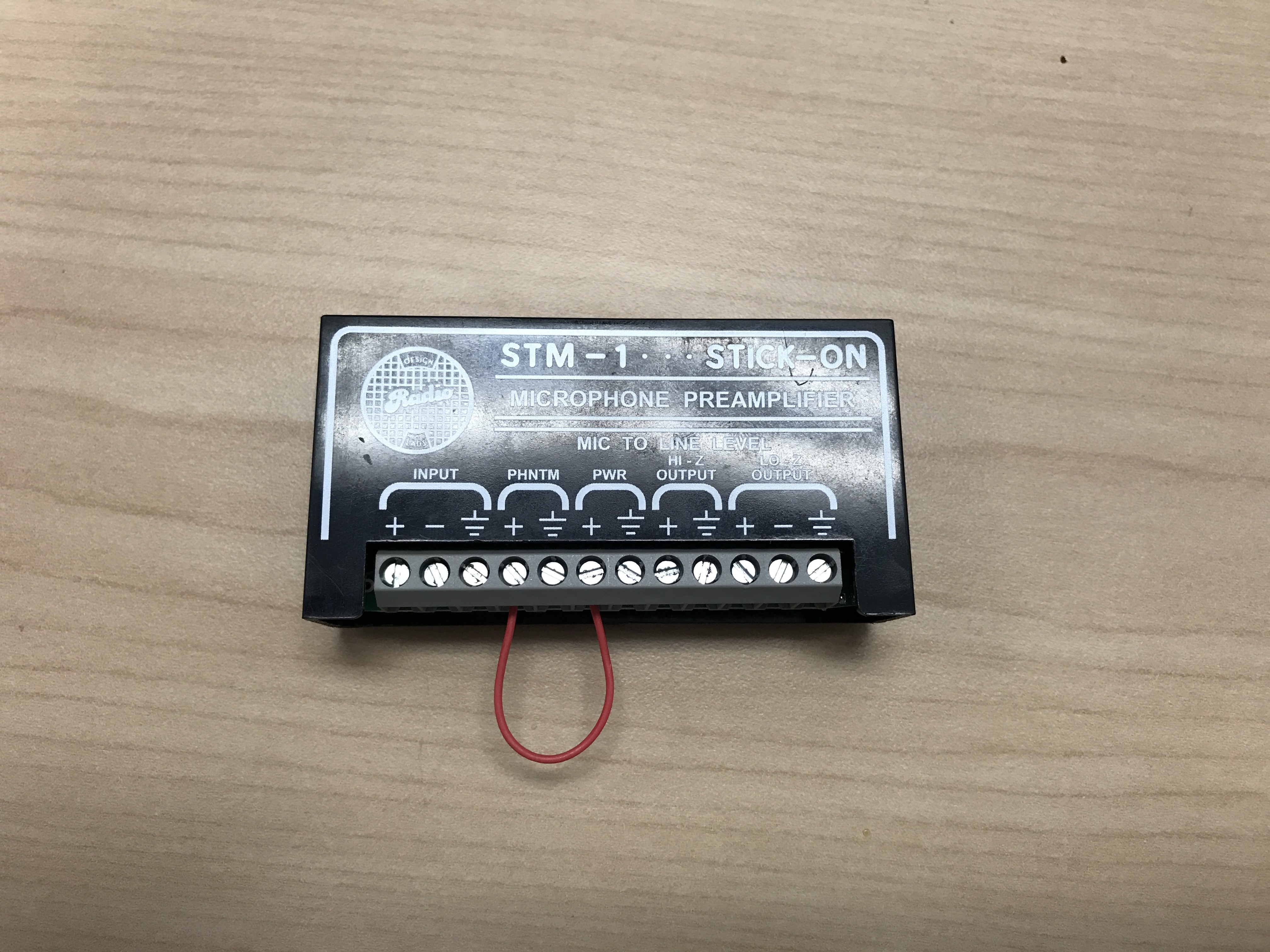
- Cut a short piece of 22/2 cable (approx. 1 inch). Strip the jacket and from the cable and remove all contents keeping only the red cable. On both ends of the red cable, strip off a piece of the jacket (See picture).
-
- Connect one end of the 1 inch audio cable to the +PWR terminal and connect the other end into the +PHNTM terminal.
-
- Connect the cable ran for power to both PWR terminals (Red to +, Black to the other terminal) of the STM-1. Connect the other side to the IO phoenix connector (Red to 2, Black to 1).
- Connect the cable ran for audio to both HI-Z OUTPUT terminals (Red to +, Black to the other terminal) of the STM-1. Connect the other side to the audio in portion of the audio phoenix connector (Red to +, Black to –).
-
- Using the Velcro that comes with the STM-1, attach the STM-1 to the wall above drop ceiling hidden from sight.
- The microphone will be connected via the input terminals of the STM-1 (Red to +, Black to -, ground to the ground terminal).
(NOTE: If there are 2 cameras in the room, duplicate these steps to get to the 2nd camera. HI-Z output can feed 2 cameras, but no more. If there are 2 Shure MX202i Microphones, duplicate steps. An STM-1 can power and gather audio from 2 Shure 202i mics.)
Connecting and Mounting the Microphone
- Asses the drop ceiling to decide best mounting placement for the MX202i. Avoid tiles adjacent to HVAC or fire safety devices.
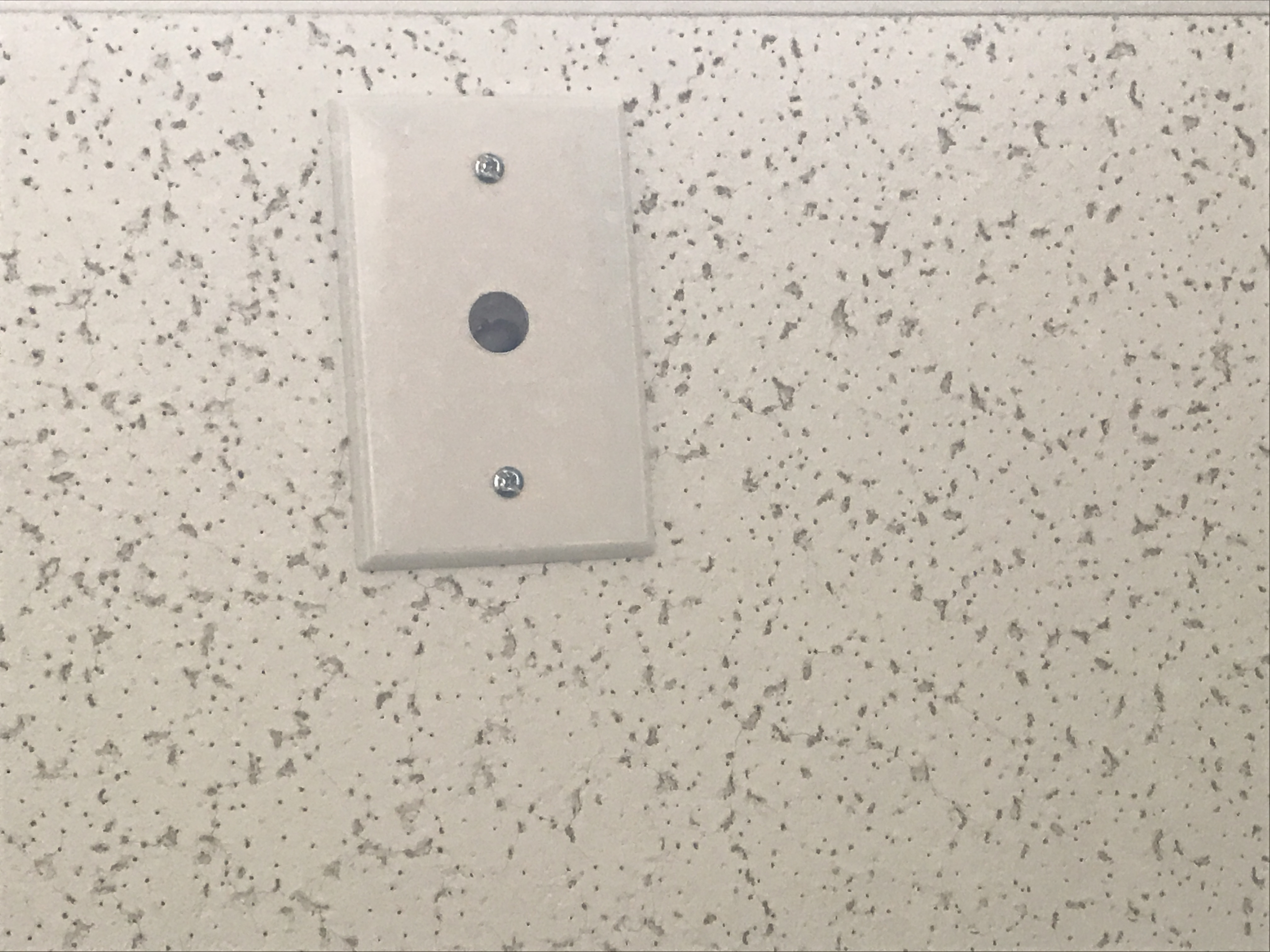
- Drill a hole into the center of the single gang plate using the ½” paddle bit (if not prefabricated).
- Measure center of the drop ceiling tile and drill a similar hole with the ½” paddle bit.
- Align the single gang plate to the location of the microphone on the drop ceiling tile using a pair of toggle bolts.
-
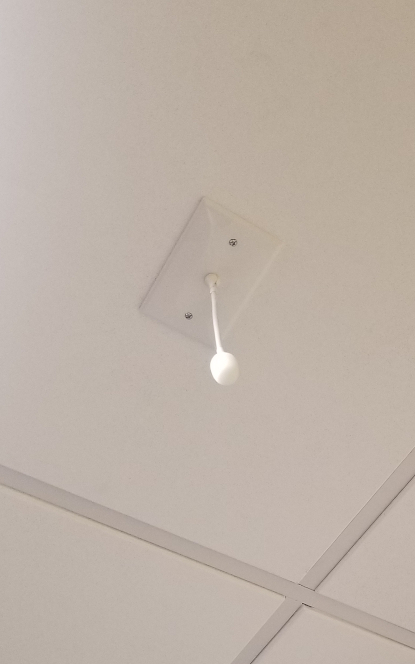
- Run the MX202i through the ½” hole in the ceiling tile and single gang plate with the rubber stopper to secure the microphone in place and plugging the ½” hole .
- Adjust the length of the cable of the microphone to a desirable length, hiding the remainder in the ceiling near the STM-1. Attach the windscreen to the MX202i.
-
- Run the XLR mini cable to the STM-1 location.
- Connect the connect the XLR mini to the 4 pin Male XLR adapter.
- Strip away a portion of the red and black cables inside the pigtail, revealing the copper wire inside.
- The microphone will be connected via the input terminals of the STM-1 (Red to +, Black to -, ground to the ground terminal).
- Connect the female XLR to the Male XLR adapter