Installing an Axis P5635-E with a Louroe Verifact D
Contents
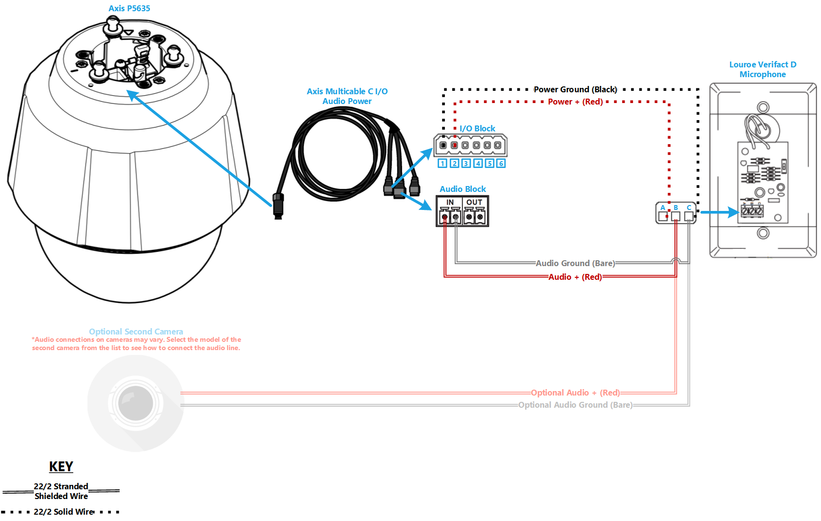
Wiring Diagram
Select Optional Second Camera
![]() Axis P3235
Axis P3235
![]() Axis P3245
Axis P3245
![]() Axis P3364/P3365
Axis P3364/P3365
![]() Axis P3374/P3375
Axis P3374/P3375
![]() Axis Axis F41
Axis Axis F41
![]() Axis P5414/P5415
Axis P5414/P5415
![]() Axis Axis M5525
Axis Axis M5525
![]() Axis Axis P5635
Axis Axis P5635
![]() Axis P5655
Axis P5655
![]() Axis V5914/V5915
Axis V5914/V5915
![]() Axis Q8414
Axis Q8414
Required Parts And Tools
- Axis P5635
- AXIS T94A02L Recessed Mount (If mounting to drop ceiling)
- Louroe IFPX
- 3.5mm (Male to Male) Audio Cable
- Louroe Verifact D Microphone
- Axis MultiCable C I/O Audio & Power
- Axis Push-Pull connector
- T10 security bit
- Wire Stripper
- Tap-Cons (if mounting to concrete) (3/16")
- Screws and Anchors (3/16")
- Toggle Bolts (If mounting to drop ceiling tile) (3/16")
- Drill bit and drill
- Phillips head drill bit or Phillips head screwdriver
- Small Flat head screwdriver (#3)
- Shielded Stranded 22/2 + ground Wire
- Razor / box cutter
- B-Connectors
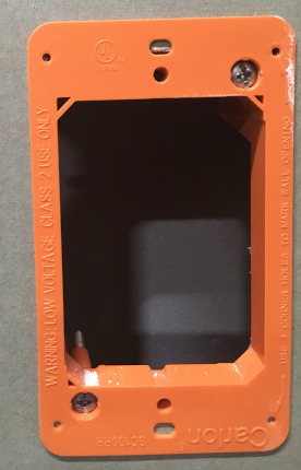
- 1 Mud ring (if mounting to drywall)
- 1 Datacom box (if mounting to hard surface (ex. Cinderblock))
- Drywall Saw
Installation Instructions
Note: There is no need to disassemble the 5635 camera.
Mounting the Camera
- Locate the network drop above the ceiling either being a male Ethernet end (service loop) or a biscuit jack. This will have been ran back to the POE switch.
- Note: If the switch does not have POE, a POE injector will need to be installed at the network closet.
- Remove Axis T94A02L kit from packaging. This will include the mounting bracket and the camera dome ring.
- Determine the location where the 5635 will be mounted and remove the ceiling tile
- Measuring the ceiling mount bracket, note that there is a slight lip to the camera mount
-
- Find center of the ceiling tile and using a pencil, draw a circle approximately nine inches in diameter
- Using a drywall saw, cut out the section of ceiling tile where the mount will be inserted
-
- Using a T20 bit, tighten the mounting arms of the ceiling mount
-
- Note: Ensure not to over tighten into the ceiling tile.
-
- Pass the Axis MultiCable C I/O and the Ethernet cable through the hole at the top of the camera mount
-
- Connect cables to their respective ports
-
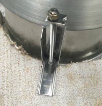
- Before locking the 5635 to the mounting posts in the ceiling mount, ensure that the safety cable is attached to the camera
-
- Insert the camera into the ceiling mount and twist until locked in place securely
-
- Using a T20 bit, secure the dome ring to the camera mount
-
- Carefully return the ceiling tile to its location


Note: If not using drop ceiling, use alternate instructions inside of the box for mounting to a hard ceiling.
Connecting Wiring
- Begin but cutting two lengths of 22/2. Ensure they are long enough to reach the microphone location. One will be for audio signal. One will be for power.
- Strip the jacket off the 22/2, revealing the red, black, and common (bare wire) on both sides of the cable.
- Remove the string and plastic casings covering the red and black cables.
- Strip the red and black jackets off the wire exposing the copper. Cut copper evenly on both ends. Remove ground.
- At the Axis MultiCable C I/O, connect the ends of 22/2
- Audio will be connected to the "In" on the audio terminal block - Red to +, Black to -
- Power will be connected to the I/O terminal block - Red to to 2, Black to 1

Connecting the Microphone
- Using a stud finder, scan the mounting location of the Verifact D ensure the microphone is not mounted on a stud.
- Cut a hole into the drywall, large enough to fit the mud ring into it securely.
-
- Using the hole saw, drill a hole above the drop ceiling in line with the hole drilled where the Verifact D is mounted.
- Feed one end of the the 22/2 audio cables through the hole. (If mounting on a hard surface, attached Datacom box to the wall).
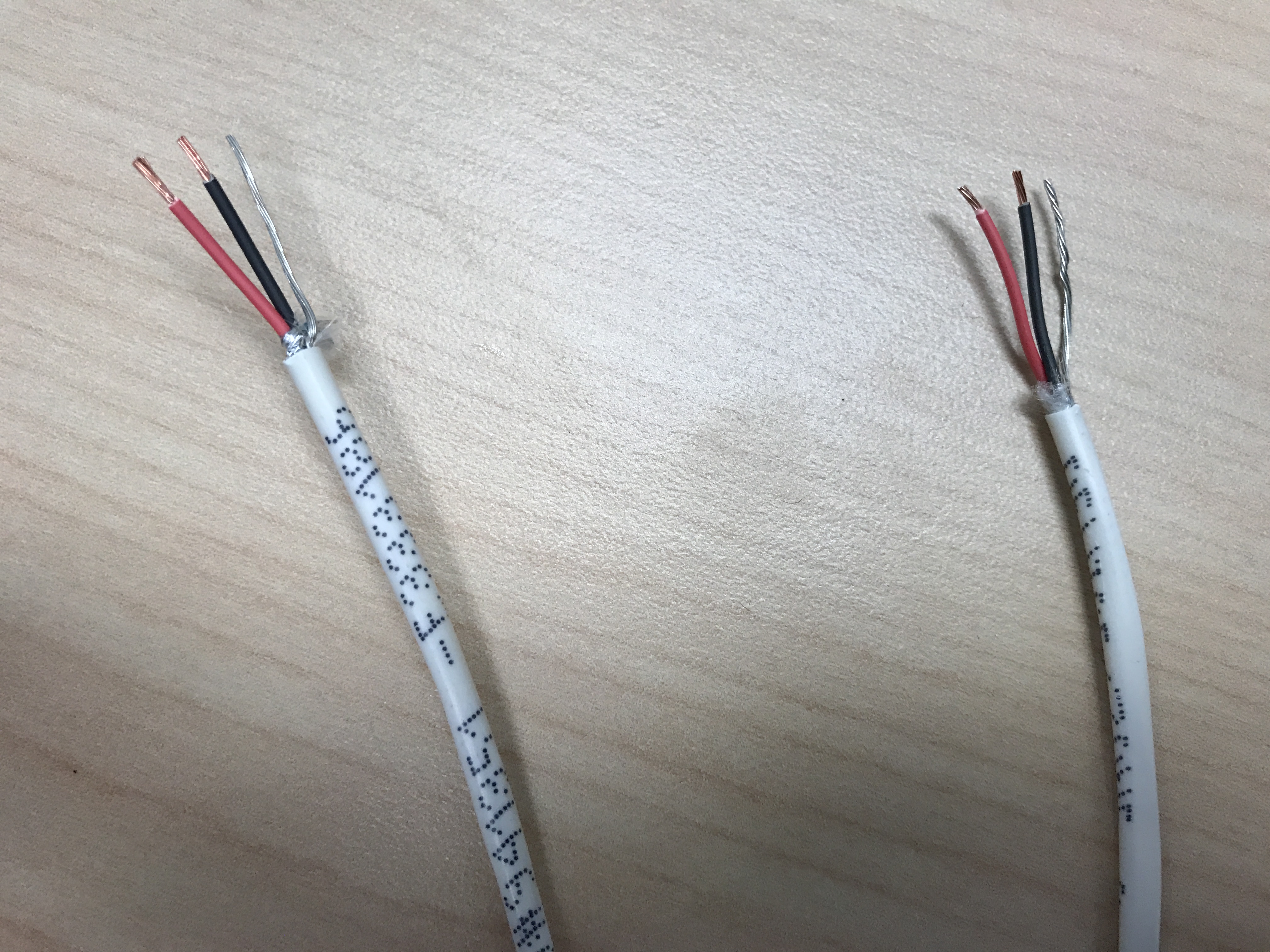
- Strip the jacket off the 22/2, revealing the red, black, and common (bare wire) on both sides of the cable.
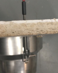
- Remove the string and plastic casings covering the red and black cables. Strip the red and black jackets off the wire exposing the copper. Cut copper evenly on both ends (See picture)
-
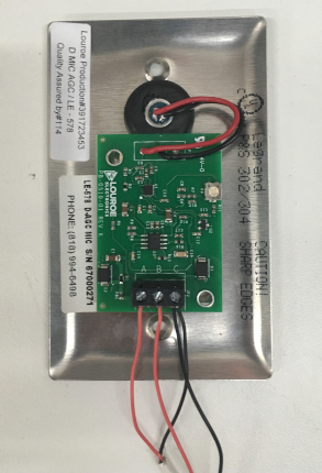
- Connect the 22/2 cables to the Verifact-D phoenix terminal as follows; Audio - Red to B, Black to C, Power - Red to A, Black to C (See Picture).
-
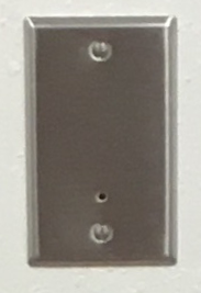
- Align Verifact-D with mud ring or Datacom box and screw in securely.
-