Installing an Axis Q8414 with a Tesira Forte DSP
Contents
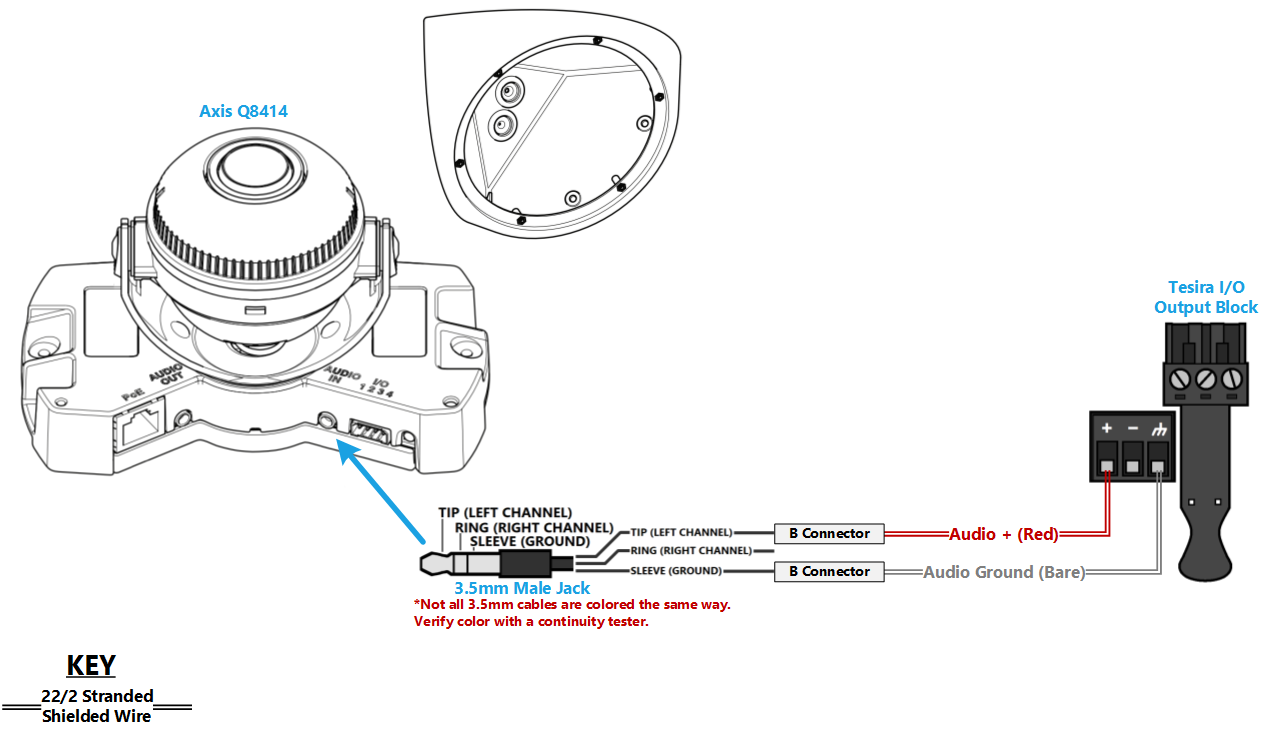
Wiring Diagram
Required Parts And Tools
- Axis Q8414
- Louroe IFPX
- 3.5mm (Male to Male) Audio Cable
- Louroe Verifact D Microphone
- T20 Torx security bit
- Wire Stripper
- Tap-Cons (if mounting to concrete) (3/16")
- Screws and Anchors (3/16")
- Toggle Bolts (If mounting to drop ceiling tile) (3/16")
- Drill bit and drill
- Phillips head drill bit or Phillips head screwdriver
- Small Flat head screwdriver (#3)
- Cat5/6 Patch Cable (7ft-15ft recommended)
- Shielded Stranded 22/2 + ground Wire
Installation Instructions
- Locate the network drop above the ceiling either being a male Ethernet end (service loop) or a biscuit jack. This will have been ran back to the POE switch. If the switch does not have POE, a POE injector will need to be installed at the network closet.
- Depending on the material of the ceiling, use a 1" paddle bit or a wall dozer to drill a hole in the corner of the ceiling to run the network drop and 3.5 mm audio cable.
- Remove the camera from the wall mount casing. Remove the gaskets from the back and side panels. With the mount placed in it's install location, make marks for the side and top screws.
- Drill holes for the mounting screws. Place the gaskets back into the side holes.
- Run the network drop and 3.5 mm audio cable through the ceiling. Secure the mount into place. As you do this, you will want to run the network cable through the top back hole, and the audio cable through the bottom hole. Drill the screws into the side holes, using the washers provided.
- Pull the network and audio cables through the gaskets, and drag the gaskets into place in the back holes.
- Guide the network and audio cable through the cable tunnels to the back of the camera, and plug them in (the pink port is AUDIO IN).
- Carefully adjust the cables, feeding them back into the ceiling if need be, to keep them from being pinched behind the camera as we mount it to the bracket. Make sure the IR window is in the 6 o'clock position; attach the camera using the T20 bit.