Installing an Axis V5914/V5915 with a Sure MX202i Microphone
Contents
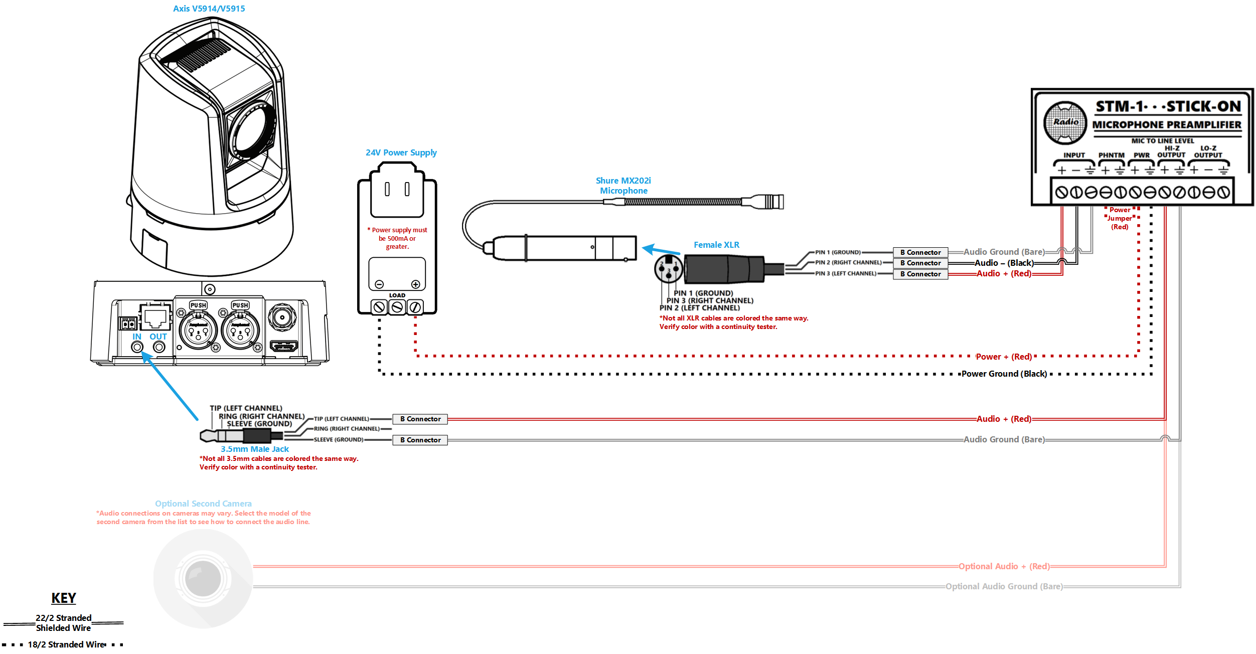
Wiring Diagram
Select Optional Second Camera
![]() Axis P3235
Axis P3235
![]() Axis P3245
Axis P3245
![]() Axis P3364/P3365
Axis P3364/P3365
![]() Axis P3374/P3375
Axis P3374/P3375
![]() Axis Axis F41
Axis Axis F41
![]() Axis P5414/P5415
Axis P5414/P5415
![]() Axis Axis M5525
Axis Axis M5525
![]() Axis Axis P5635
Axis Axis P5635
![]() Axis P5655
Axis P5655
![]() Axis V5914/V5915
Axis V5914/V5915
![]() Axis Q8414
Axis Q8414
Required Parts And Tools
- Axis V5914/V5915
- RDL STM-1
- Female XLR Pigtail
- Shure MX202i Microphone
- T10 security bit
- Wire Stripper
- 1/2" paddle bit
- 1 blank single gang wall plate
- Toggle Bolts (If mounting to drop ceiling tile) (3/16")
- Tap-Cons (if mounting to concrete) (3/16")
- Screws and Anchors (3/16")
- Drill bit and drill
- Phillips head drill bit or Phillips head screwdriver
- Small Flat head screwdriver (#3)
- Hole Saw (2")
- B Connectors
- Cat5/6 Patch Cable (7ft-15ft recommended)
- Shielded Stranded 22/2 + ground Wire
- Fish Tape or Glow Rods
- Wind Screen (Inside MX202i kit)
- Rubber Stopper (Inside MX202i kit)
- 4 pin XLR-M to XLR-M Adapter (Inside MX202i kit)
- 3.5mm Audio Cable
- RDL PS-24AS
Installation Instructions
Drop Ceiling Mount Instructions
NOTICE: The combined weight of the camera and mounting bracket is approximately 1.7 kg (3.7 lb.). Make sure that the ceiling material is strong enough to support this weight. The ceiling tile should be 5–60mm (0.2–2.4in.) thick.
- Locate the network drop above the ceiling either being a male Ethernet end (service loop) or a biscuit jack. This will have been ran back to the POE switch.
- Note: If the switch does not have POE, a POE injector will need to be installed at the network closet.
- Remove the ceiling tile in which the drop ceiling mount is to be fitted.
- Drill a 7 mm (9/32 in) hole in the ceiling tile.
- Drill about a 1" hole where the cables will pass through into the ceiling.
- Remove the tripod screw from the mounting bracket.
- Attach the short end of the threaded rod to the camera and tighten.
- Assemble the camera, ceiling tile and the mounting bracket, and tighten the nut.
- Route and connect all cables to the camera (network, audio, power, possible HDMI, possible I/O cable).
- Connect the power supply to a mains power outlet (100–240 VAC).
- Install the ceiling tile with the camera mounted on it.
- Connect the 4 Pin XLR-M end of the MX202i to the 4 pin XLR-M adapter. Next, run that mic cable to the back of the V59 camera XLR-F input 2 (L).
- Connect the power supply to a mains power outlet (100–240 VAC).
- Install the ceiling tile with the camera mounted on it.
Wall Mount Instructions
- Use a stud finder to locate wall studs, and determine proper placement for the L bracket.
- Make a mark for the 3 screw holes on the short end of the L bracket, and the area to fish the cables (3/16" wall screws and anchors used here).
- Drill the holes for the anchors
- Using a hole saw, to drill a hole to fish cables
- Place the anchors and screw the bracket down
- Using glow rods or fish tape, fish the cables (power, network, 3.5mm audio, possible 22/2 for I/O, and possible HDMI cables) down the ceiling through the hole under the bracket.
- Place the V59 onto the bracket, and secure it with the tripod screw from underneath.
- Route and connect all cables to the camera (network, audio, power, possible HDMI, possible I/O cable).
- Connect the 4 Pin XLR-M end of the MX202i to the 4 pin XLR-M adapter. Next, run that mic cable to the back of the V59 camera XLR-F input 2 (L).
Connecting the STM-1
- You will need to cut a short piece of 22/2 cable (approx. 1 inch). Strip the jacket from the cable, and remove all contents keeping only the red cable. On both ends of the red cable, strip off a piece of the jacket (See picture).
- Connect one end of the 1 inch audio cable to the +PWR terminal and connect the other end of that into the +PHNTM terminal.
- Strip the wiring on the PS-24AS revealing the 2 copper wires inside. Connect the copper to the PWR terminals (White striped to +, Solid Black to the other terminal) of the STM-1.
- Connect 22/2 to the LO-Z OUTPUT terminals (Red to +, Black to -, Bare Wire to Ground) of the STM-1. Ensure you run enough 22/2 cable to your V5914/V5915
- Connect the audio cable that is intended for your microphone to the input terminals of the STM-1 (Red to +, Black to -, Common to the common terminal). Using the Velcro that comes with the STM-1, attach the STM-1 to a safe place (preferably keeping it out of sight).


(NOTE If there are 2 cameras in the room, duplicate step 4 using a long enough cable to get to the 2nd camera. If there are 2 Shure MX202i Microphones, duplicate step 5.)
- Cut the 3.5mm cable in half (one end should already be plugged into the camera. Strip away the jacket exposing the insides. Strip away the red and white jackets in the 3.5mm cable exposing the copper insides. You will need to use a cable tester to check for polarity (the red/white leads are not necessarily positive/negative.) Splice the 3.5mm cable to the 22/2 audio cable coming from the LO-Z output (Red to +, White to -, Copper to Copper). Secure these connections with B-Connectors.


Connecting and Mounting the Microphone
- Asses the drop ceiling to decide best mounting placement for the MX202i. Avoid tiles adjacent to HVAC or fire safety devices.
- Drill a hole into the center of the single gang plate using the ½” paddle bit (if not prefabricated).
- Measure center of the drop ceiling tile and drill a similar hole with the ½” paddle bit.
- Align the single gang plate to the location of the microphone on the drop ceiling tile using a pair of toggle bolts.
- Run the MX202i through the ½” hole in the ceiling tile and single gang plate with the rubber stopper to secure the microphone in place and plugging the ½” hole .
- Adjust the length of the cable of the microphone to a desirable length, hiding the remainder in the ceiling near the STM-1. Attach the windscreen to the MX202i.
- Run the XLR mini cable to the STM-1 location.
- Connect the connect the XLR mini to the 4 pin Male XLR adapter.
- Strip away a portion of the red and black cables inside the pigtail, revealing the copper wire inside.
- The microphone will be connected via the input terminals of the STM-1 (Red to +, Black to -, ground to the ground terminal).
- Connect the female XLR to the Male XLR adapter

