OWI Overhead Speaker Installation Instructions
From IVS Wiki
Required Parts And Tools
- OWI Amplified Overhead Speaker
- 3.5mm audio cable
- 22/2 shielded audio cable
- 18/2 low voltage cable
- Drywall saw
- B Connectors
- Wire Stripper
- 22/2 audio cable
- Fish Tape or Glow Rods
- Electrical Tape
Installation Instructions
Mounting Instructions
- Determine the most optimal placement for the OWI speaker
- Note: Avoid mounting adjacent to microphones to prevent signal looping
- Remove the ceiling tile to which the speaker will be mounted
- When removing the speaker from its packaging, note that there is a cutting template for the speaker. Ensure to remove the excess along the dashed line
- Using the cutting template, trace the template centered in the ceiling tile
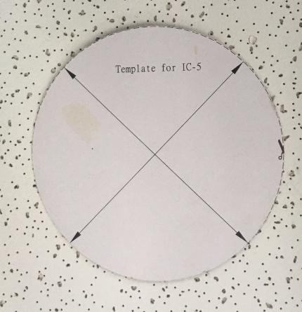
- Using a drywall saw, carefully cut out the mounting location
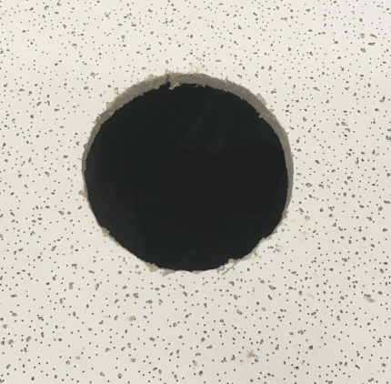
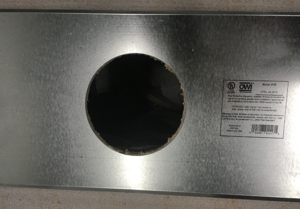
- Flip the ceiling tile over and align the tile mounting plate with the cut hole.
- Using a small tool, carefully remove the screen from the speaker. This is necessary in order to secure the mounting arms.
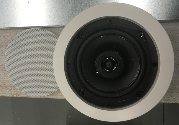
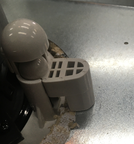
- With one hand on the speaker, insert the speaker into the mounting location and tighten the mounting arms securely to the mounting plate
- Note: It is easiest to get one arm nearly secured and adjust the mount plate before securing all four arms.
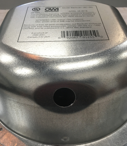
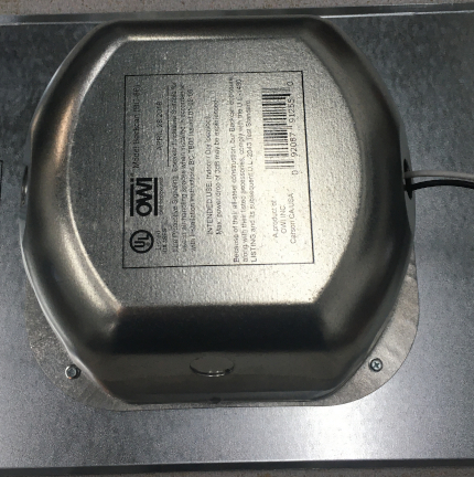
- Tap out the appropriate hole on the back of the speaker housing
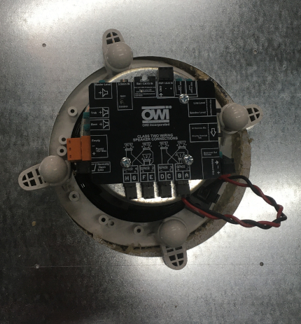
- Connect the wiring before securing the speaker housing using the provided screws.
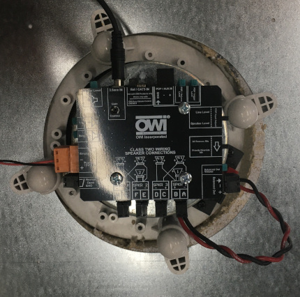
- Audio will be connected from 22/2 ran from the camera and spliced with B-connectors to a 3.5mm audio cable. Insert in the 3.5mm In port (shown below). Ensure the gain control is not set at zero both on the 3.5mm and the master level.
- Power will be connected to the phoenix terminal (shown below). Red to +, Black to -
Connecting to Power
- Determine if power is available above the ceiling or at outlet height.
- If running power to an outlet, determine the best location and route for running 18/2.
- Using a stud finder, scan the wall as near as possible to the power outlet, ensuring to not mount on a stud and remaining level with the power outlet.
- Cut a hole into the drywall, large enough to fit the mud ring into it securely.
- Using fish tape and glow rods, fish the 18/2 through the drywall.
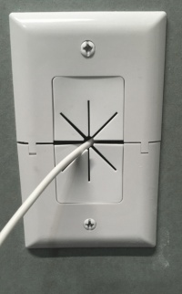
- Once the 18/2 is through the cut hole, insert the mud ring and secure the cable pass through plate
- Strip back the shield of the 18/2 and the black and red wires.
- Using B-connectors, splice the power brick to the 18/2
- Plug in the power block. A small pop may be heard from the speaker upon receiving power.
Connecting the Camera
- Once your camera is installed, locate the AUDIO OUT on your camera.
- Strip the jacket of the 22/2 cable revealing the red, black, and bare wires inside.
- Cut away the plastic surrounding the cable inside. Strip away a small piece of the red and black jackets revealing the bare copper wire.
- Wire the black and bare to the - and the red to the + of the AUDIO OUT of the phoenix connector.
- Run the 22/2 cable from the camera to the AMP2SIC5, wiring your red wire to the + phoenix connection and black to the - connection of the LINE INPUT of the AMP2SIC5
- Run the 18/2 from the AMP2SIC5 to its designated power outlet.


