Public Talkback - Decora In Wall Speaker
From IVS Wiki
Required Parts And Tools
- Output Speaker (may be overhead or in wall mounted)
- Shure MX393 Boundary Mic
- RDL STM-1 Preamp
- XLR Tail
- RDL ST-VOX1
- RDL DBPSP
- RDL 24V power supply
- Single Decora face plate
- Drill
- Drywall Saw
- 22/2 audio cable
- B-connectors
- Crimper
- Fish Tape or Glow Rods
- Stud Finder
- Electrical Tape
- Wire Stripper
- Pencil
Installation Instructions
Mounting the Speaker
- Determine the best placement for the speaker in the room.
- Using a stud finder, scan to ensure the placement is viable
- Note: If installing on a medical head wall, make sure there is an appropriate path for wiring.
- Using a drywall saw, cut out the location the speaker will be mounted.
- Using glow rods or fish tape, pass two lines of 22/2 behind the wall, one for audio and one for power.
- Note: Install a pass through plate for power if necessary and/or if power is not available above the ceiling.
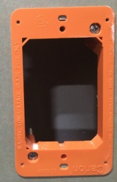
- Secure the mudring
- Connect the wiring to the respective ports
- Using the provided screws, secure the speaker to the mud ring
- Secure the decora faceplate
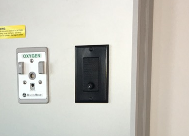
Mounting the Audio
- Decide where the STM-1 will be located, knowing the MX393 mic will need to reach it.
- Using a stud finder, determine the best location to route the 22/2 cable
- Cut a hole into the drywall, large enough to fit a mud ring into it securely.
-
- Using glow rods or fish tape, pass the 22/2 behind the wall routing to the STM-1
- Secure a pass through plate to the mud ring mounted for the XLR just ran
- Place the MX393. Splice the XLR tail to 22/2 using B connectors. This mic line will connect the mic line to the STM-1
- Note: The wires of the XLR will wire to the +, -, and ground Input on the STM-1.
- Mount the STM-1 above the ceiling
- Wire the red to the + and black to the ground power terminals on the STM-1.
- Cut a length of 22/2 from the STM-1 to the camera. Strip the jacket on both ends. Cut away the bare wire and plastic surround the cable inside. Strip away a small piece of the red and black jackets revealing the bare copper wire.
- A short piece of 22/2 cable will also be needed (approx. 1 inch).
- Strip the jacket from the cable and remove all contents keeping only the red cable.
- On both ends of the red cable, strip off a piece of the jacket. Connect one end of the 1 inch audio cable to the +PWR terminal and connect the other end into the +PHNTM terminal.
- Run another length of 22/2 cable from the STM-1 to the a ST-VOX1
Wiring the ST-VOX1
- Connect a line from the High Z of the STM-1 to the ST-VOX1 to the center port of the input on the device labeled as a line diagram (see wiring diagram)
- From the Camera, run three lines of 22/2. One will be connected to the input and two will be connected to the output.
- Connect the 22/2 connected to the camera input to the first port on the line diagram input. Connect one of the 22/2 connected to the camera output to the input port labeled Line. The third 22/2 will connect to the speaker.
- Note: All lines connected to the ST-VOX1 utilize shared ground

