Recording LED
Contents
Required Parts and Tools
- VALT LED Recording Light Indicator
- Phillips Screw Driver
- Wire Stripper
- B Connectors
- Mud Ring
- 22/2 Shielded or Unshielded cable
- Stud Finder
- Fish Tape or Glow rods
Preparation
- Cut a hole in the sheet rock wall at the location where the LED indicator will be mounted. The hole should be approximately 2 1/8 inches x 3 5/8 inches.
- Insert the mud ring into the hole and tighten it down using the screw driver.
Wiring
- Using fish tape or a wire fish, run 22/2 up through the wall and to the camera.
- Connect the 22/2 to the camera
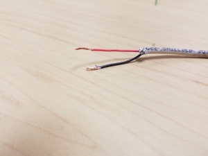
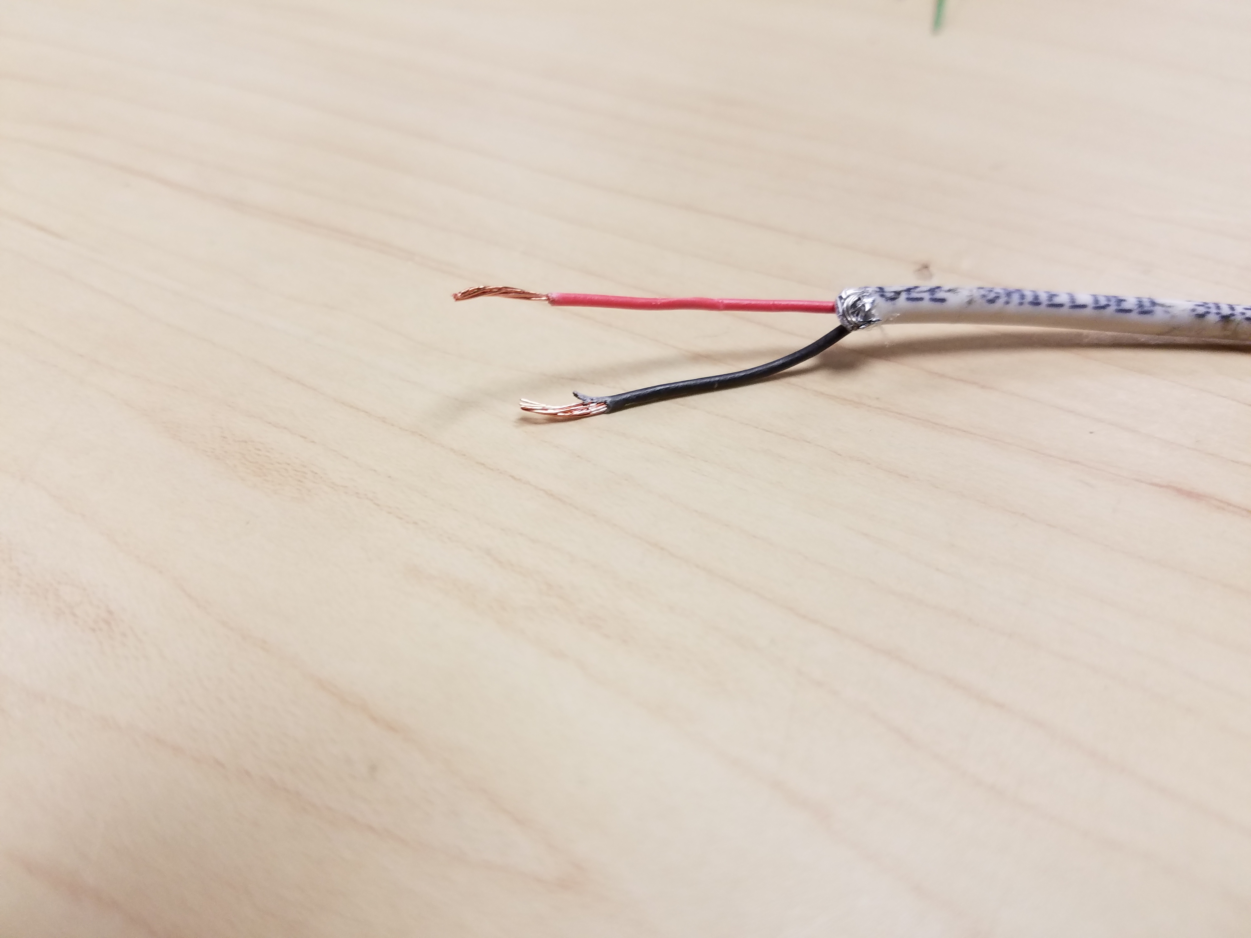
- Strip approximately 1 inch of the outer insulation from each end of the 22/2 wire.
- Strip approximately 1/4 inch off the insulation for the black and red conductor on each end of the 22/2 wire.
- Insert the red wire into the number 2 I/O port on the camera. If necessary, trim the wire before inserting to ensure no bare wire is exposed.
- Insert the black wire into the number 4 I/O port on the camera. If necessary, trim the wire before inserting to ensure no bare wire is exposed.

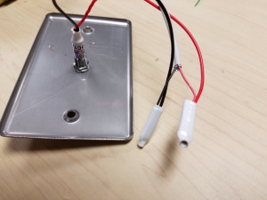
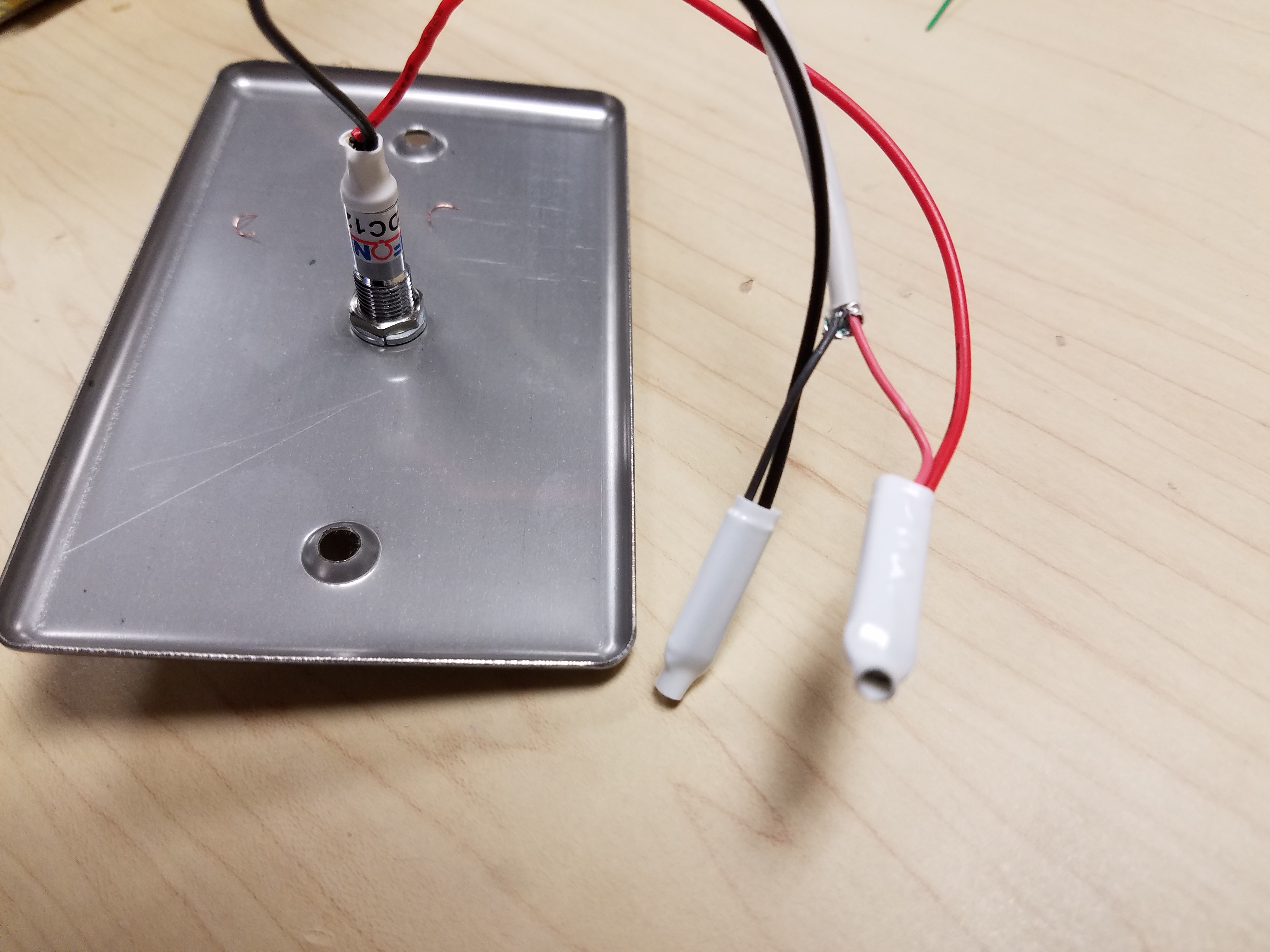
- Connect the 22/2 to the VALT LED Recording Light Indicator.
- Strip approximately 1 inch of the outer insulation from each end of the 22/2 wire.
- Strip approximately 1/2 inch off the insulation for the black and red conductor on each end of the 22/2 wire.
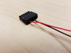
- Splice the red wire to the positive (typically the red wire) on the VALT LED Recording Light Indicator.
- Splice the black wire to the ground (typically the black wire) on the VALT LED Recording Light Indicator.
- Insert both splices into separate B Connectors and crimp the connectors.
Mounting
Screw the metal faceplate of the VALT LED Recording Light Indicator to the mud ring using the included screws.
Camera Configuration
Depending on the model of Axis camera, you may need to set the second I/O port on the camera to an output.
- Navigate to the camera's IP address in a web browser
- If prompted, enter the username and password for the camera.
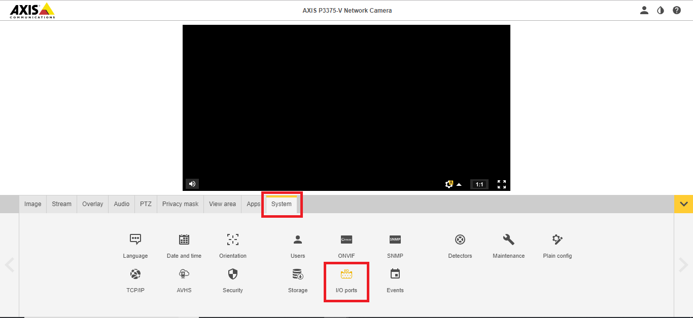
- Click on System; click on Ports
-
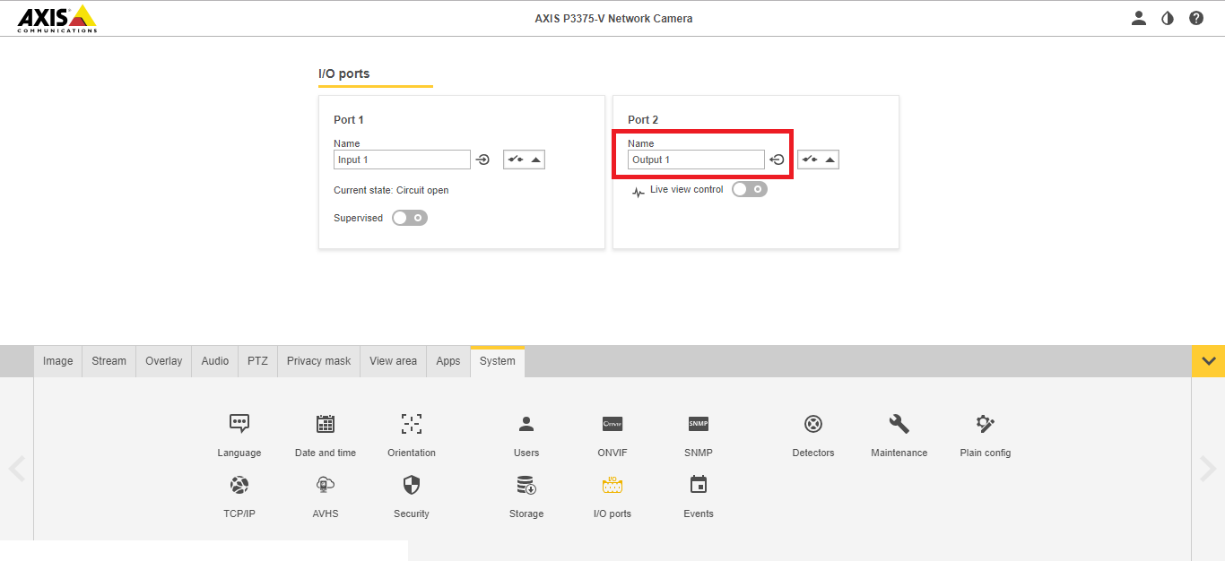
- Ensure that I/O Port 2 is set to Output.
-
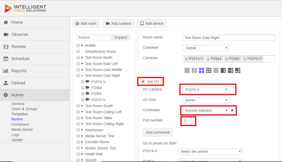
VALT configuration
- Head to the Admin Tab.
- Select the room including our camera.
- Check the "Use I/O" box.
- Select the camera in question as the I/O Camera.
- In the "Command" field, select "Record Indicator".
- Enter Port number 2.