Speaker Selector Configuration
Contents
Description/Objective
This is an example with a Control Room Audio Solution in a nursing sim lab. In this example, there are two speakers in the sim room; an overhead speaker for communication and instructions, and a PSP in-wall speaker to communicate as the dummy patient. The customer is requesting a User Interface to select the speaker for their talkback audio at a moment's notice. This means we will also build a Canvas User Interface (this will be covered in another section). Before building in Canvas, it is crucial to create the Tesira configuration properly.
Physical Wiring/Line Diagram
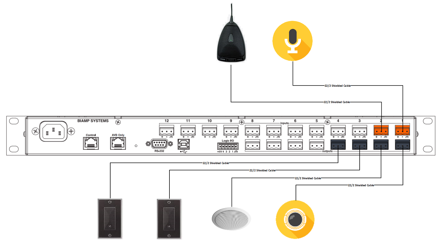
Below is the physical wiring diagram.
Tesira Software
Connections
- If the physical connections are complete, open the Tesira software and start building a configuration.
- In this configuration use the following blocks:
- TesiraFORTE CI block
- Peak Meter x 3
- Uber Filter x 2
- Level Block with 2 ports
- Compressor with "ganged mode" and "advanced curve"
- Matrix Mixer with 2 inputs and 5 outputs
- Standard Mixer with 2 inputs and 2 outputs (this will become the microphone selector in Canvas)
- Connect the blocks as follows:
- Connect a peak meter to the Tesira Input block. This will help ensure proper levels are set on the preamp.
- Connect the AEC block to the Uber Filters, then the Filters to the Level Block.
- Connect the Level Block to the Compressor and the second Peak Meter.
- Connect the Compressor to the Matrix Mixer.
- Connect outputs 1 & 2 from the Matrix Mixer to the Output block and peak meter.
- Connect output 3 from the Matrix Mixer to the Standard Mixer.
- Connect the outputs from the Standard Mixer to the output block and the peak meter.
- Connect outputs 4 & 5 from the Matrix Mixer to the AEC Reference.
- Matrix Mixer: The sim room mic will be sent to three places; the camera, the control room speaker, and the AEC reference for the push to talk mic. The push to talk mic will be sent 3 places; the camera, the Standard Mixer (renamed 'speaker selector' in this config), and the AEC reference for the room mic.
- The Standard Mixer sends the push to talk audio to two places; the overhead speaker and the PSP in-wall patient speaker.
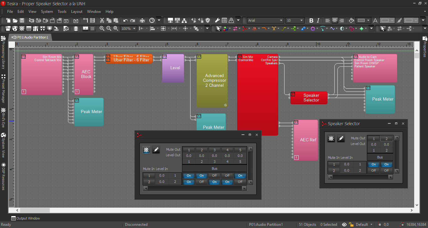
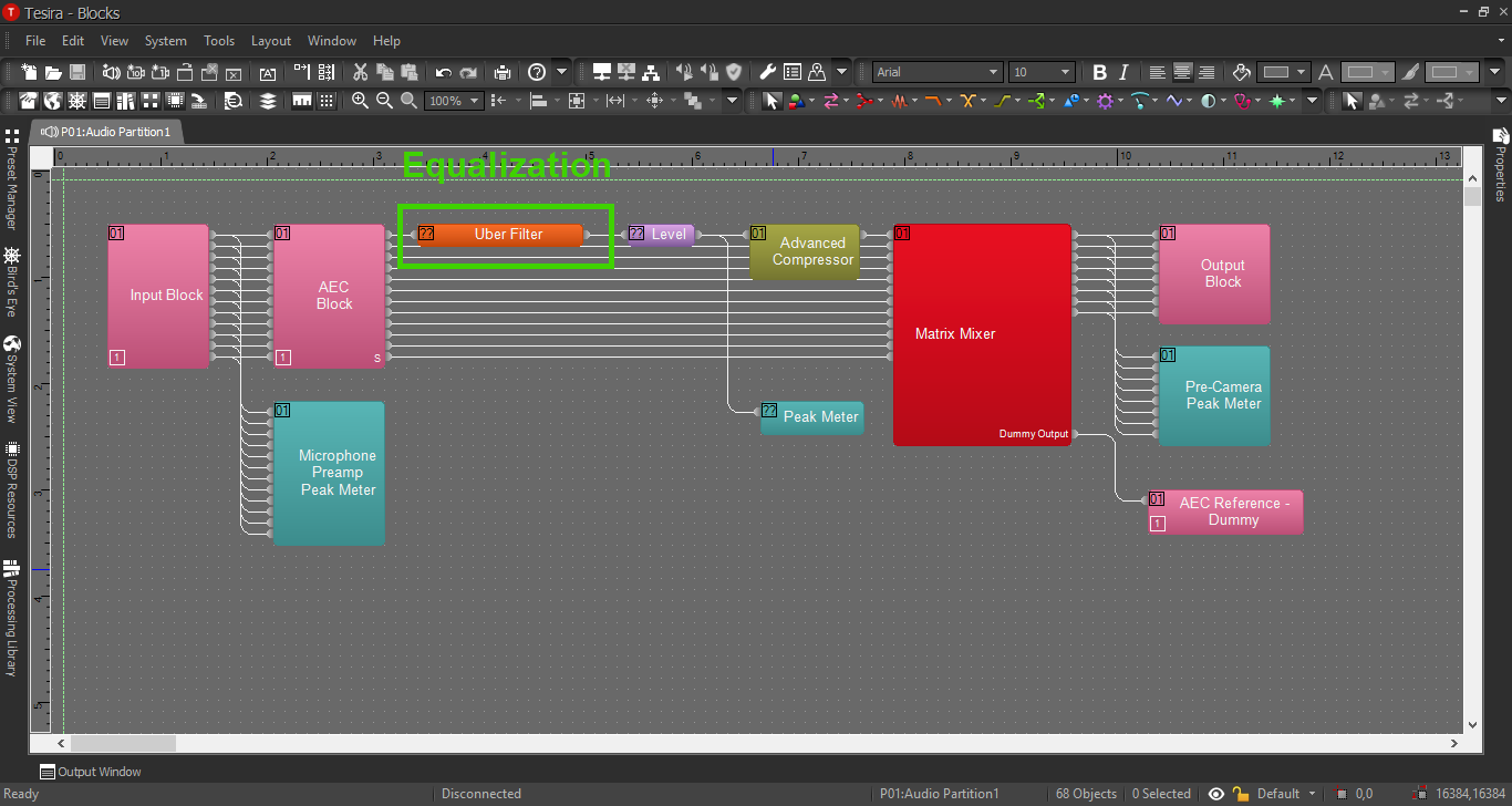
When this is complete, the file should look something like this:
Creating a Canvas User Interface
In another section, we will build the corresponding Canvas UI configuration for the Speaker Selector. Click the image below:
Processing Blocks in Tesira
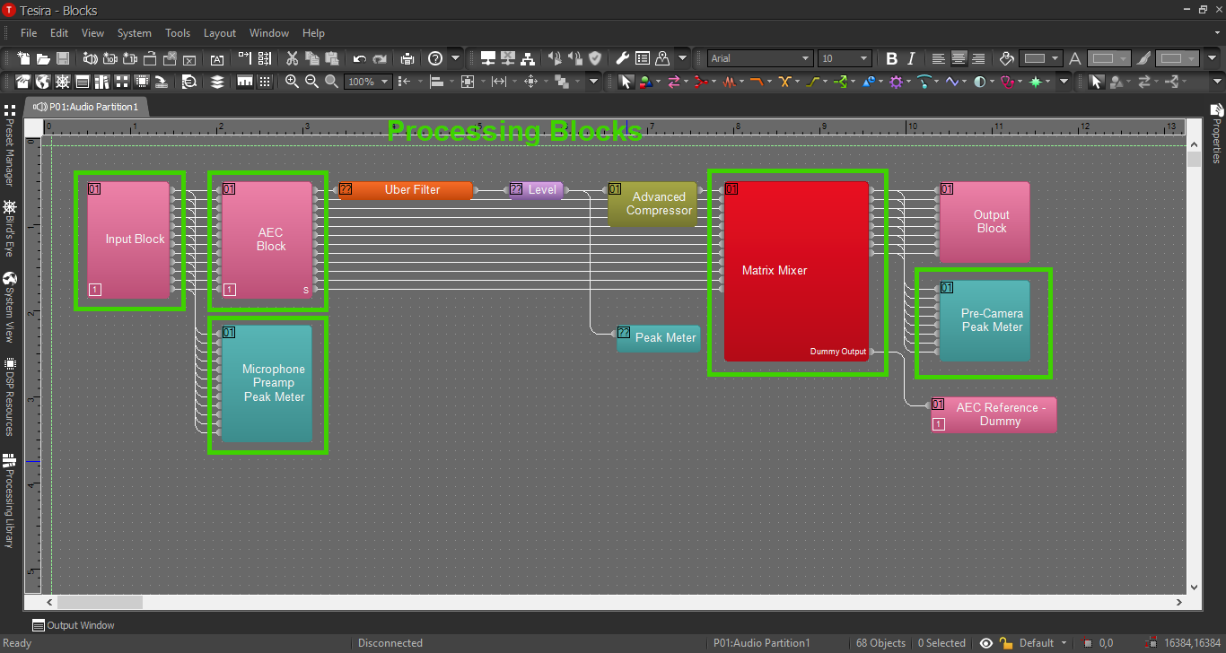
For further insight about the other processing blocks and settings, refer back to the first configuration example, or click the image below:
EQ and Compression
For information on EQ settings, or click the image below:
For Compression parameters, click the image below:
