Template:Connecting The Microphone Shure MX202i STM1
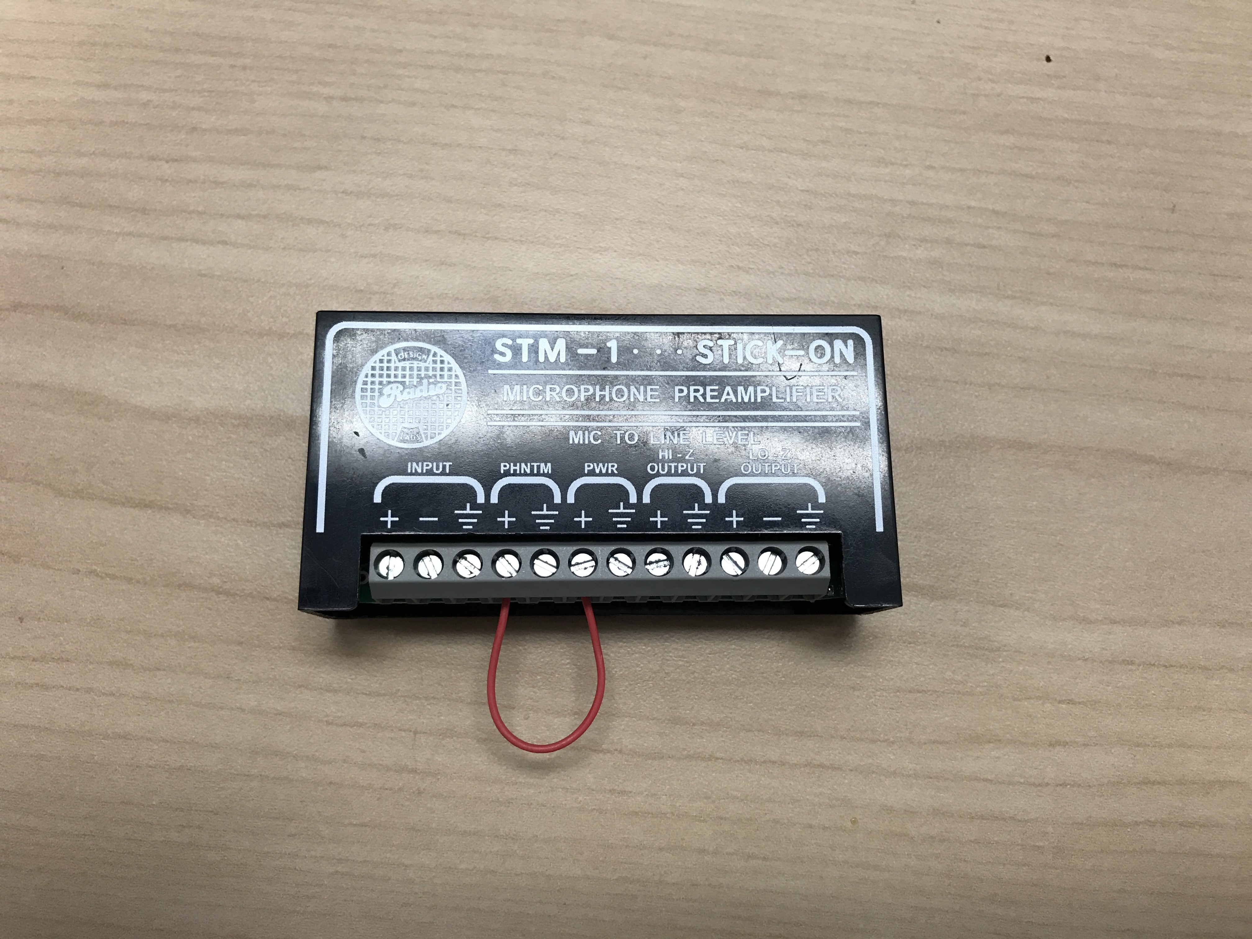
Connecting the STM-1
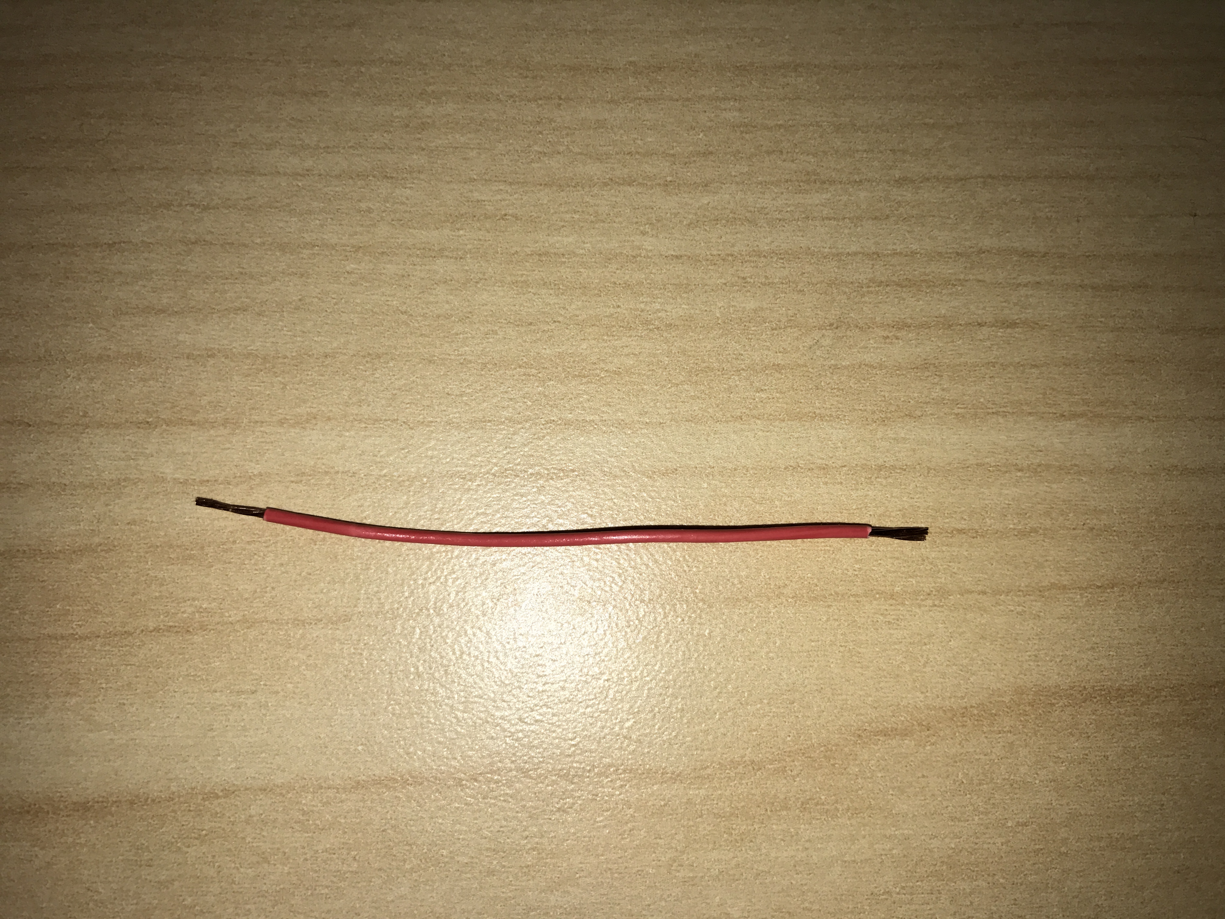
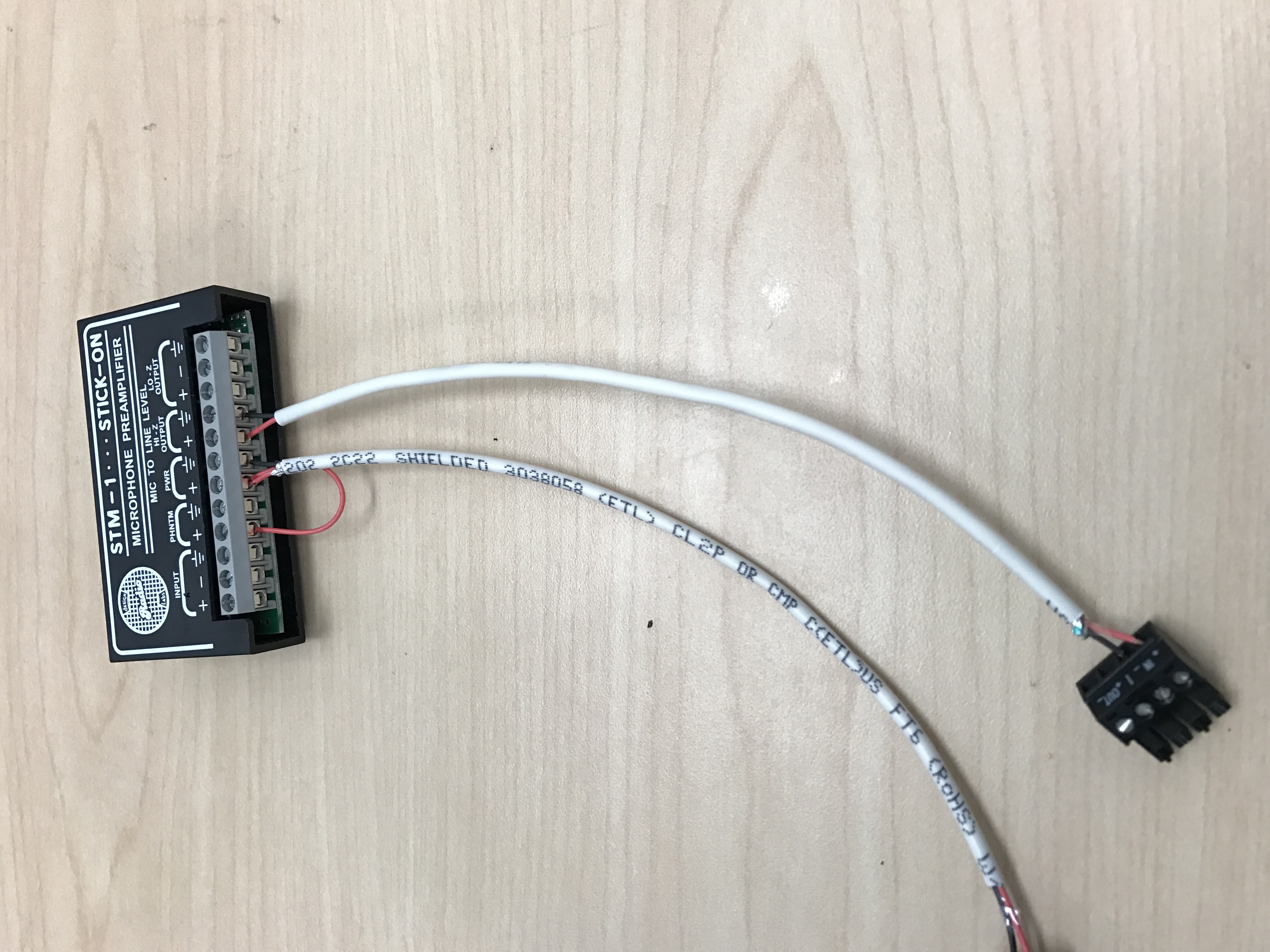
- Cut a short piece of 22/2 cable (approx. 1 inch). Strip the jacket and from the cable and remove all contents keeping only the red cable. On both ends of the red cable, strip off a piece of the jacket (See picture).
-
- Connect one end of the 1 inch audio cable to the +PWR terminal and connect the other end into the +PHNTM terminal.
-
- Connect the cable ran for power to both PWR terminals (Red to +, Black to the other terminal) of the STM-1. Connect the other side to the IO phoenix connector (Red to 2, Black to 1).
- Connect the cable ran for audio to both HI-Z OUTPUT terminals (Red to +, Black to the other terminal) of the STM-1. Connect the other side to the audio in portion of the audio phoenix connector (Red to +, Black to –).
-
- Using the Velcro that comes with the STM-1, attach the STM-1 to the wall above drop ceiling hidden from sight.
- The microphone will be connected via the input terminals of the STM-1 (Red to +, Black to -, ground to the ground terminal).
(NOTE: If there are 2 cameras in the room, duplicate these steps to get to the 2nd camera. HI-Z output can feed 2 cameras, but no more. If there are 2 Shure MX202i Microphones, duplicate steps. An STM-1 can power and gather audio from 2 Shure 202i mics.)
Connecting and Mounting the Microphone
- Asses the drop ceiling to decide best mounting placement for the MX202i. Avoid tiles adjacent to HVAC or fire safety devices.
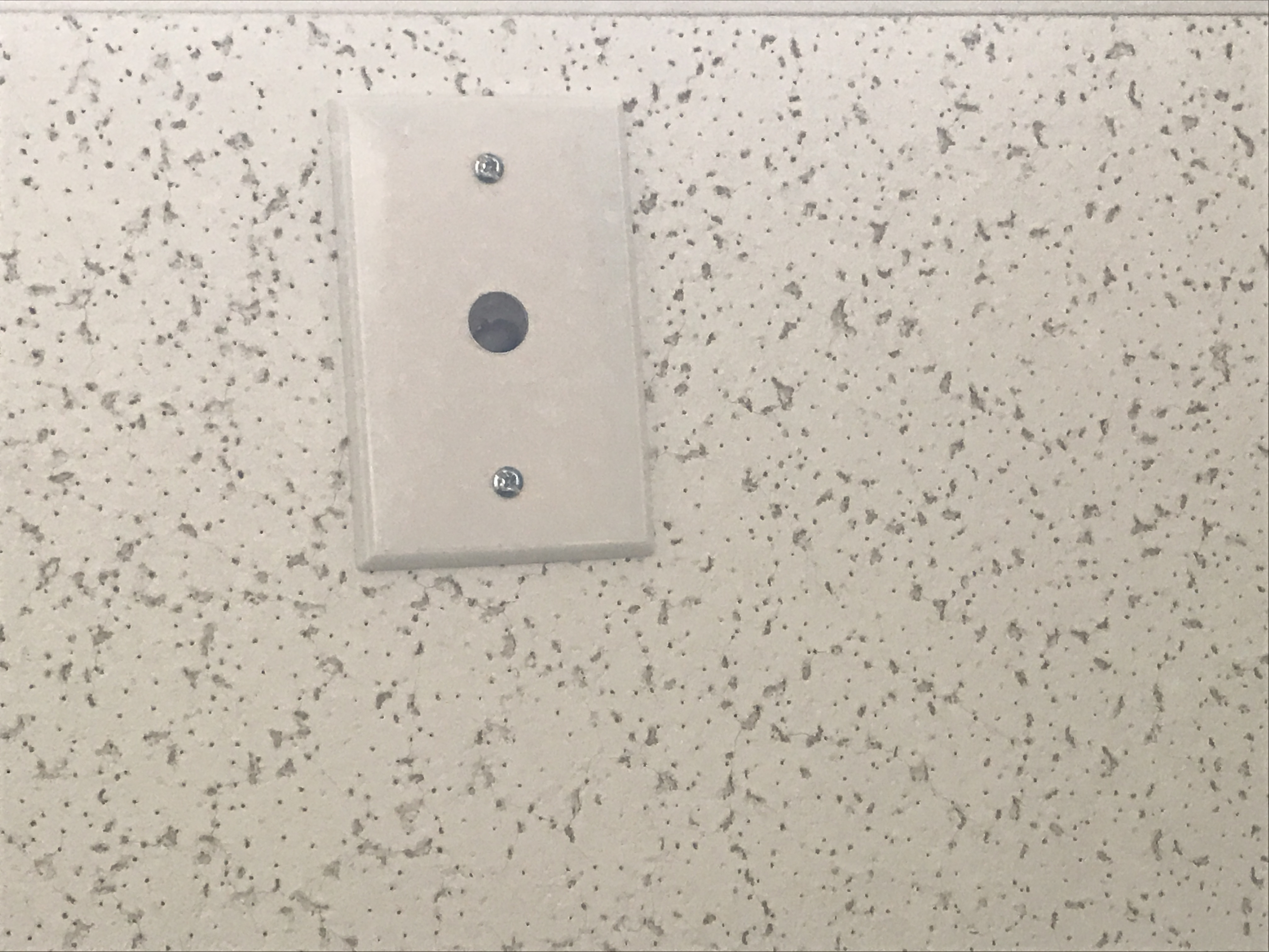
- Drill a hole into the center of the single gang plate using the ½” paddle bit (if not prefabricated).
- Measure center of the drop ceiling tile and drill a similar hole with the ½” paddle bit.
- Align the single gang plate to the location of the microphone on the drop ceiling tile using a pair of toggle bolts.
-
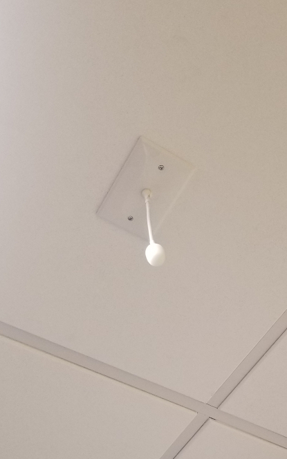
- Run the MX202i through the ½” hole in the ceiling tile and single gang plate with the rubber stopper to secure the microphone in place and plugging the ½” hole .
- Adjust the length of the cable of the microphone to a desirable length, hiding the remainder in the ceiling near the STM-1. Attach the windscreen to the MX202i.
-
- Run the XLR mini cable to the STM-1 location.
- Connect the connect the XLR mini to the 4 pin Male XLR adapter.
- Strip away a portion of the red and black cables inside the pigtail, revealing the copper wire inside.
- The microphone will be connected via the input terminals of the STM-1 (Red to +, Black to -, ground to the ground terminal).
- Connect the female XLR to the Male XLR adapter