Template:F41 F1015 Installation Instructions
Installation Instructions
Mounting the Processing Unit
- Locate the network drop above the ceiling. It should be terminated with a male Ethernet end (service loop) or a biscuit jack. This line will have been ran back to the POE switch.
- Note: If the switch does not have POE, a POE injector will need to be installed at the network closet.
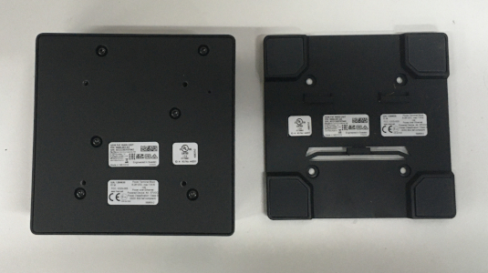
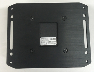
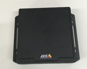
- Using the T20 bit, remove the rubber feet from the bottom of the Axis F41 Main Unit, and replace it with the Axis F8001. This will allow the F41 to be mounted to drywall above the drop ceiling.
-
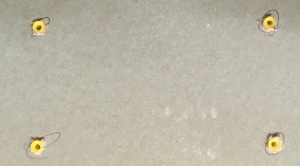
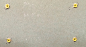
- Find the a suitable mounting location for the F41. Using a pencil, mark the location the four anchors will be mounted
- Using a drill and drill bit, drill the mounting locations.
- Insert the four anchors and screws (or wall dogs), and mount the F41 into the drywall above the drop ceiling.
- Note: if there is no drop ceiling make other arrangements for mounting.
-
-
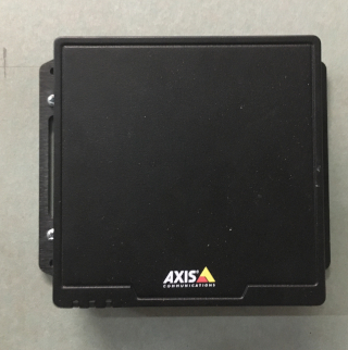
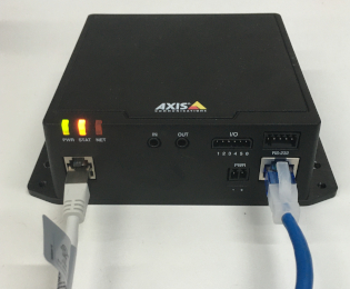
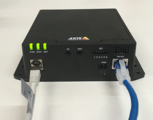
- Connect the network drop to the Axis F41 Main Unit. When connected, the NET, STATUS, and POWER LEDs will show green on the unit. After approximately one minute, all three indicators should be green.
-

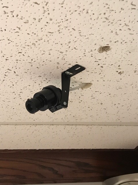
Mounting the Camera
- Assemble the mounting unit for the Axis F1015.
- Mount the camera into the drop ceiling using toggle bolts.
- Run the attached RJ-11 cable to the input labeled CAM on the Axis F41 Main Unit. Ensure to drill an appropriate hole in the drop ceiling to feed the RJ-11 cable through.
-