Template:F41 F1025 Installation Instructions
From IVS Wiki
Installation Instructions
Mounting the Processing Unit
- Locate the network drop above the ceiling. It should be terminated with a male Ethernet end (service loop) or a biscuit jack. This line will have been ran back to the POE switch.
- Note: If the switch does not have POE, a POE injector will need to be installed at the network closet.
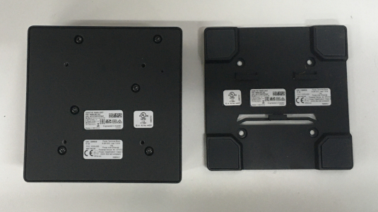
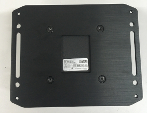
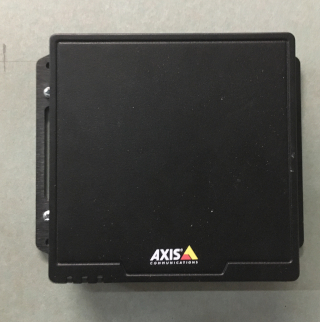
- Using the T20 bit, remove the rubber feet from the bottom of the Axis F41 Main Unit, and replace it with the Axis F8001. This will allow the F41 to be mounted to drywall above the drop ceiling.
-
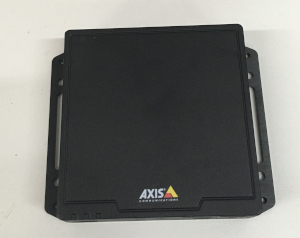
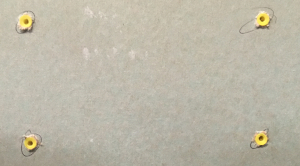
- Find the a suitable mounting location for the F41. Using a pencil, mark the location the four anchors will be mounted
- Using a drill and drill bit, drill the mounting locations.
- Insert the four anchors and screws (or wall dogs), and mount the F41 into the drywall above the drop ceiling.
- Note: if there is no drop ceiling make other arrangements for mounting.
-
-
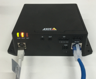
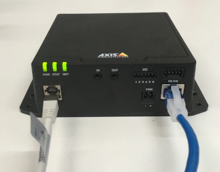
- Connect the network drop to the Axis F41 Main Unit. When connected, the NET, STATUS, and POWER LEDs will show green on the unit. After approximately one minute, all three indicators should be green.
-
Mounting the Camera
- Determine the proper mounting location for the Axis 1025
- Cut a hole into the drywall, large enough to fit the mud ring into it securely. (If mounting on a hard surface, attach Datacom box to the wall).
- Run the attached RJ-11 cable behind the drywall to the input labeled CAM on the Axis F41 Main Unit. (shown above)
Aiming the Camera
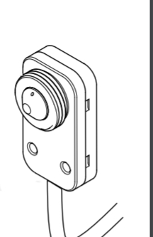
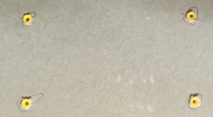
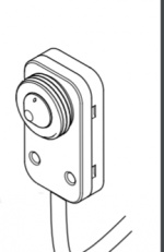
- To adjust and level the field of view, the camera barrel will need to be rotated
- Notice the small hole on the 1025 sensor (shown below). Using a tool like a small punch or paper clip, rotate the camera barrel
-
- To verify the camera image, the camera will need to be accessed using the Axis camera web portal
- If the camera is being powered off the network, run Axis IP utility in order to discover the camera. Clicking the IP address will route to the Axis web portal
-
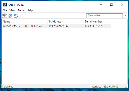
- If that does not work then use a POE injector to connect to the camera and the default IP. (default Axis IP = 192.168.0.90)
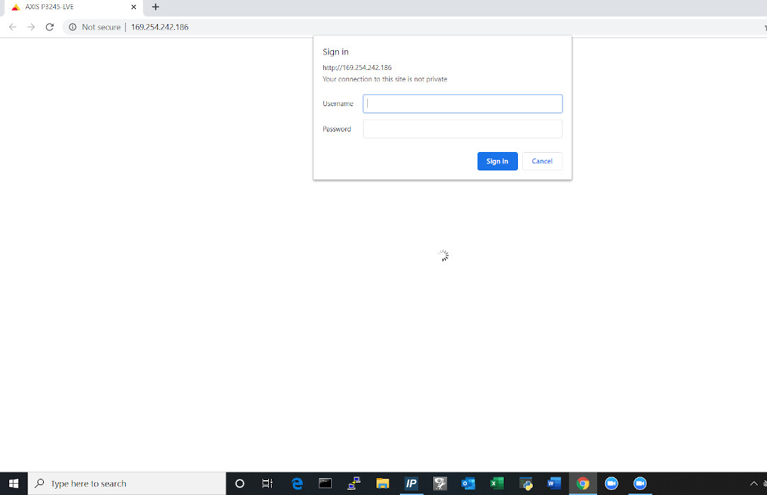
- Using a laptop/PC, enter the IP address assigned to the camera into a web browser.
-

- Using the IVS admin credentials, log into the camera.
- User: root
- Password: admin51
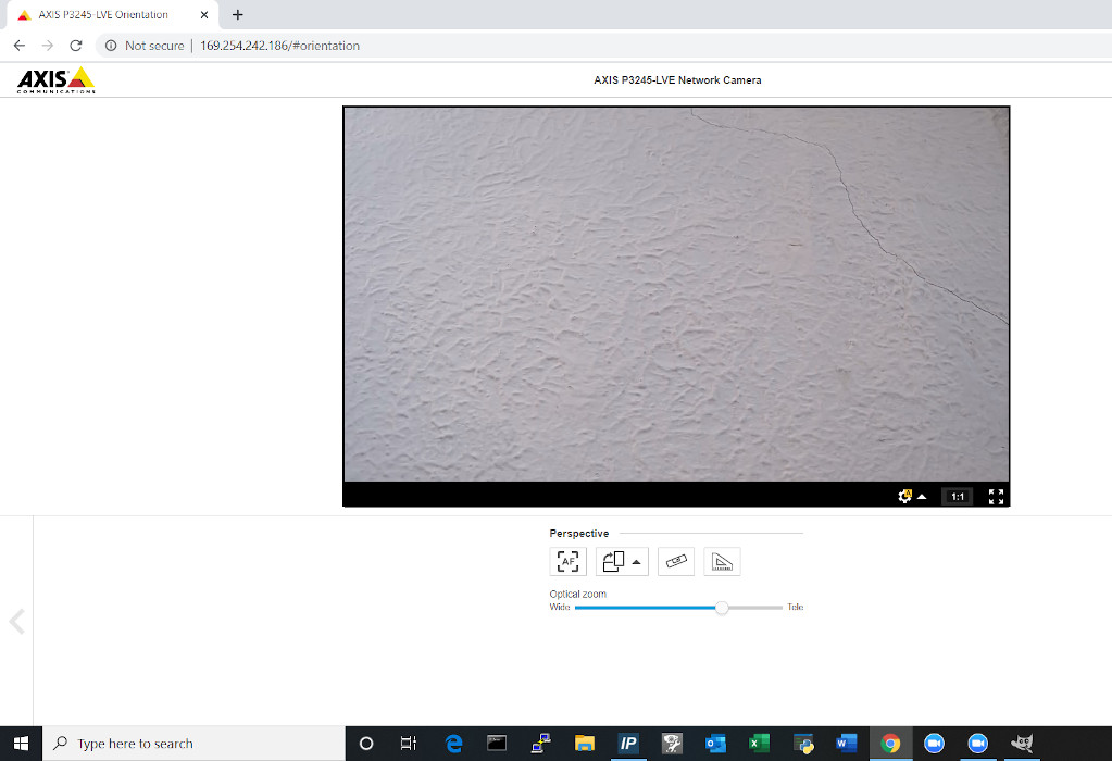
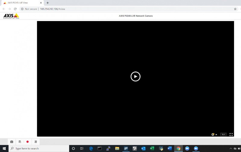
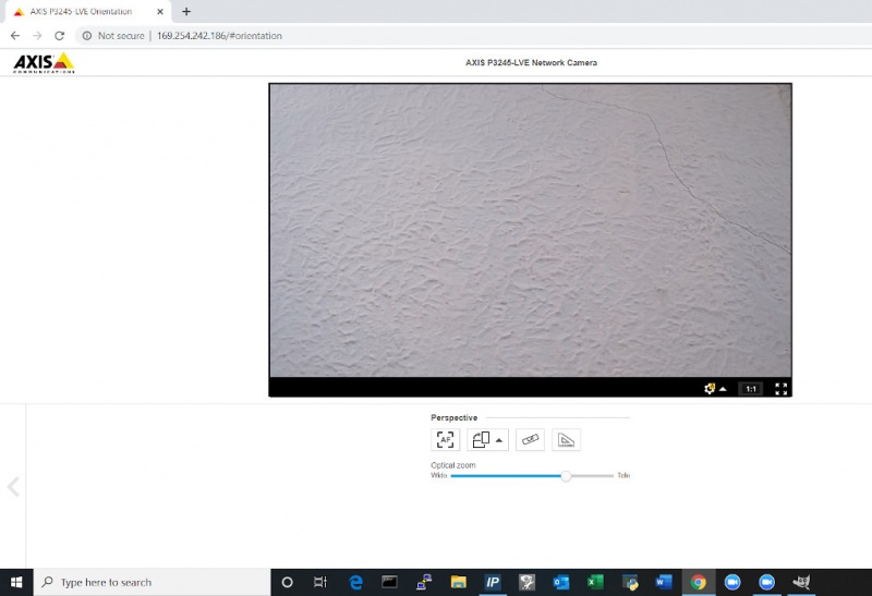
- Once in the Axis web portal, activate the camera live view.
-
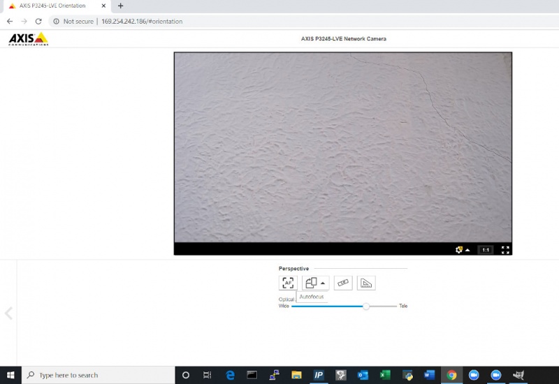
- Be sure to click the Autofocus button. This will focus the camera and ensure that the autofocus is properly functioning.
-
- Once established, secure the faceplate to the mud ring by applying a liberal amount of epoxy to the sensor body.
- Mount Axis F1025 to single gang wall plate, aligning the camera with the center cut hole.