Template:P3374 VerifactA
From IVS Wiki
Connecting the Microphone
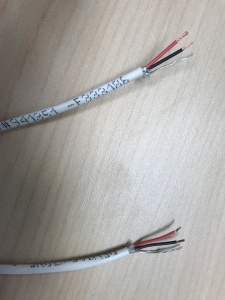
- Strip the jacket off the 22/2, revealing the red, black, and common (bare wire) on both sides of the cable.
- Remove the string and plastic casings covering the red and black cables.
- Strip the red and black jackets off the wire exposing the copper. Cut copper evenly on both ends.
- On the cable ran for power, cut off the common (bare wire) completely as it will not be used. (See picture)
- Cut a 3.5 mm audio cable in half.
- Strip about an inch of the black jacket; then strip about 1/2 inch of red and white strand jacket.
- Test the 3.5 cable for polarity (touch one end of the cable tester to the tip of the 3.5 jack and the other end to the red and white wires. This will be the positive wire; the middle section of the 3.5 jack is negative wire; the bottom section of the jack is ground/stranded wire.)
- Splice these wires with the camera end of the 22/2 cable ran for audio. Red to A, Black to B, Common (bare wire) to C (See Picture)
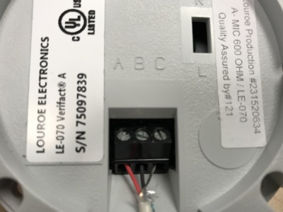
- Connect the power cable to the IO phoenix connector (Red to 2, Black to 1).
- Plug in the network drop to the camera network port, the 3.5 jack into the pink AUDIO IN port on the camera, and the IO Phoenix connector to the IO port.
- Also cut a 3” piece of 22/2 cable, but only the inner red wire. Strip ¼” of the jacket from both ends of the cable. Insert and secure this wire as a jumper from Phantom+ to Power+.
- Place the dome over on the camera. Using the T20 bit, tighten the dome cover in place.

