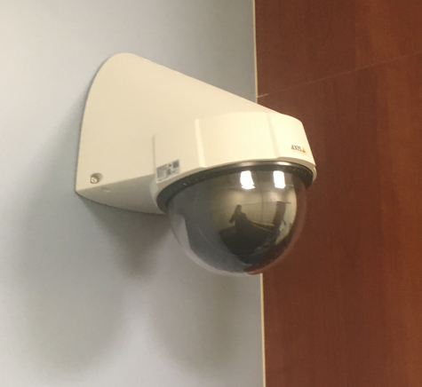
Template:P5414 Installation Instructions
From IVS Wiki
Installation Instructions
- Locate the network drop above the ceiling either being a male Ethernet end (service loop) or a biscuit jack. This will have been ran back to the POE switch providing High POE
- Note: High POE requires up to 37W for PTZ functions. If the switch does not have High POE, a POE injector will need to be installed at the network closet.
- Using a stud finder, ensure there aren’t any studs where the camera will be mounted.
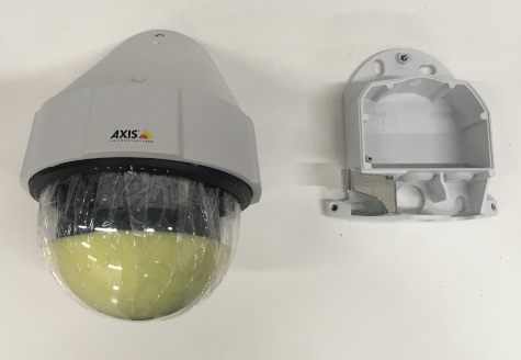
Disassembling the Camera
- Remove the P5414/P5415 camera from its base with the T20 bit.
-
- Using a small Phillips head screwdriver, remove the plastic ring around the base of the camera dome.
- Using the T10 bit, remove the camera dome and remove the protective foam.
-
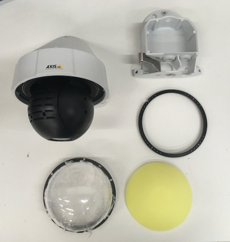
- Reattach the dome and snap the plastic ring back into place.
Mounting the Camera
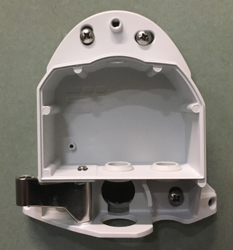
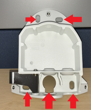
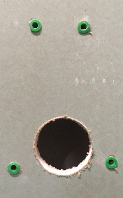
- While holding the camera base plate where it will be mounted, use a pencil to mark the 4 areas on the wall where the screws will be located. Also mark the opening where the any cabling will pass through (see image below).
-
- Using the drill bit, drill the 4 screw marks and insert mounting anchors.
- Using the hole saw (recommended size 2” inches or less), drill a hole into the area where cables will pass through.
-
- Using the hole saw, drill a hole above the drop ceiling in line with the hole drilled where the camera will be mounted.
- Note: If there isn’t any drywall above the ceiling, adjust accordingly to your circumstance.
- Using glow rods or fish tape, fish the network drop and 2 sections of 22/2 audio cable through the drywall.
- Note: The sections of audio cable should be long enough to reach the destination where the Verifact A will be mounted in ther drop ceiling. One will be for audio to the camera; the other will be to power the microphone.
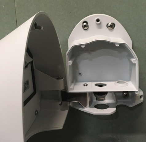
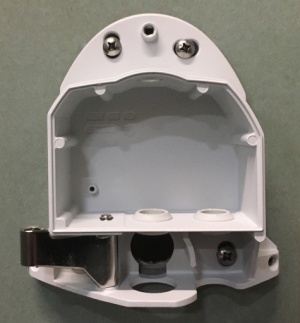
- Mount the Axis P5414/5415 base to the wall using the screws associated with the anchors.
-
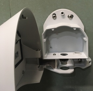
- Attach the camera to the base plate mount arm.
-
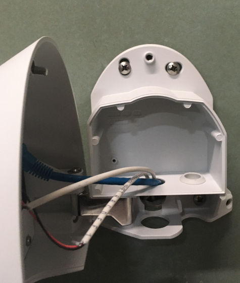
- Remove the middle rubber piece on the camera base and run the network drop and any other cabling through this hole.
-
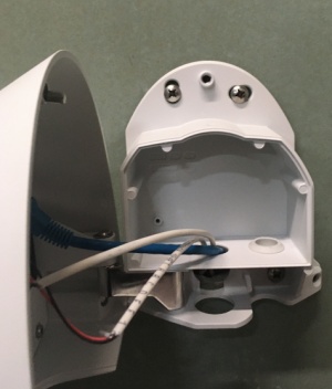
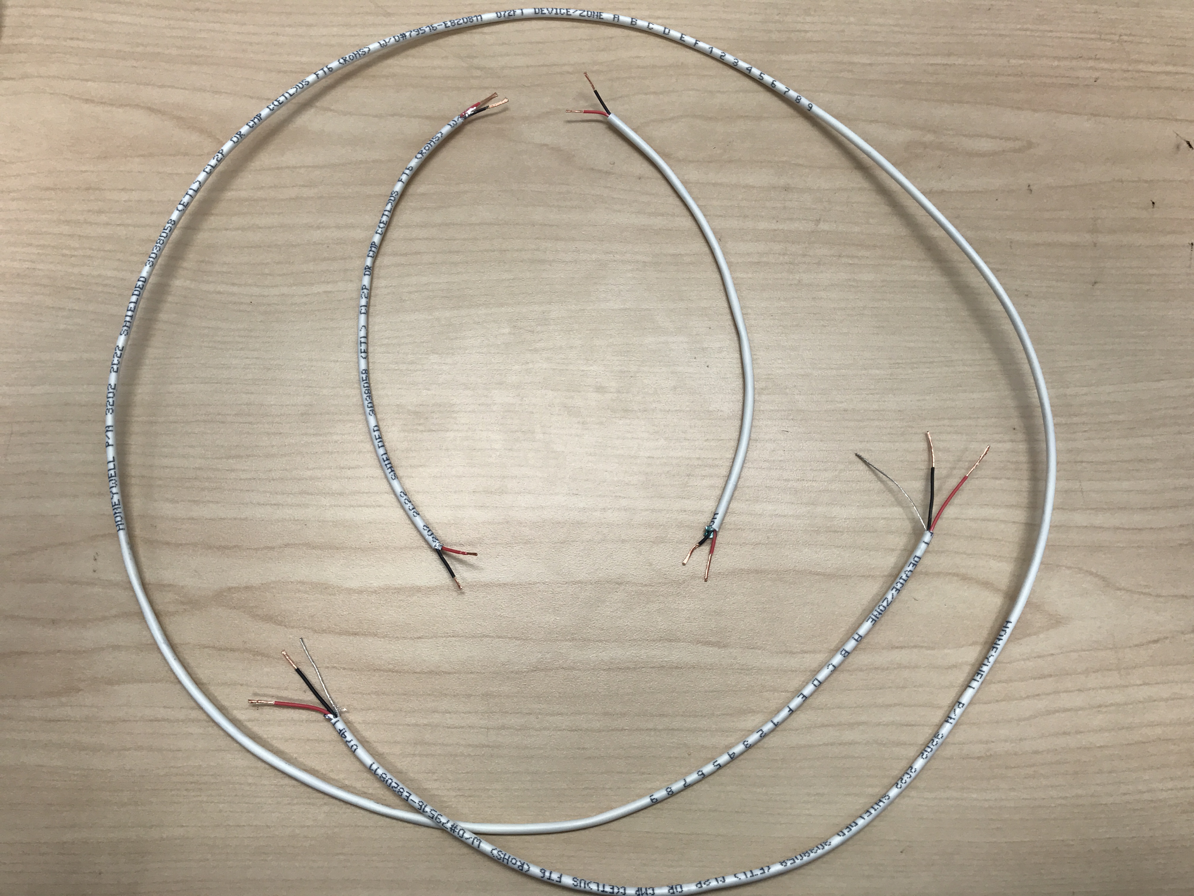
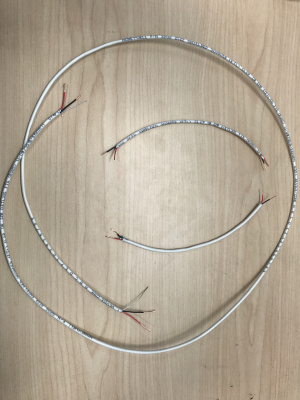
- Strip the jacket off the 2 runs of 22/2, revealing the red, black, and common (bare wire). Remove the string and plastic casings covering the red and black cables. Strip the red and black jackets off the wire exposing the copper. Cut copper evenly on both ends (See picture). On the cable for power, remove the common (bare wire) completely.
-
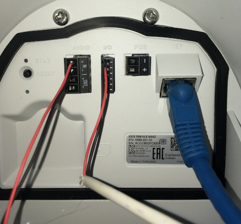
- At the camera, connect the 22/2 for audio to the audio terminal block. Red to +, Black to -
- Connect the 22/2 for power to the I/O terminal block. Red to 2, Black to 1
- Connect the Ethernet cable. The status LED will appear amber at first then change to green. When the camera is in full functionality, the LED will turn off.
-
- Using the T20 bit, attach the camera to the mounting plate at the three screw locations
- Remove the protective covering from the camera dome
-