Difference between revisions of "Unboxing Your VALT POC System"
IVSWikiBlue (talk | contribs) |
IVSWikiBlue (talk | contribs) |
||
| Line 7: | Line 7: | ||
* VALT POC Wireless Access Point | * VALT POC Wireless Access Point | ||
| − | + | {{img | file = PoCunbox1.jpg | width=400px}} {{img | file = POCunbox2.jpg | width=400px}} | |
The case will be locked with combination locks. Please contact your VALT Sales Representative for the combination. | The case will be locked with combination locks. Please contact your VALT Sales Representative for the combination. | ||
| Line 15: | Line 15: | ||
On the top layer will be the back plate VALT POC Camera and Stand | On the top layer will be the back plate VALT POC Camera and Stand | ||
| − | + | {{img | file = POCunbox3.jpg | width=600px}} | |
Remove the VALT POC Cameras (back board) and set them aside. | Remove the VALT POC Cameras (back board) and set them aside. | ||
| Line 21: | Line 21: | ||
The next element will be the VALT POC Camera base. This houses all wiring, processing, and also contains the accessory panel | The next element will be the VALT POC Camera base. This houses all wiring, processing, and also contains the accessory panel | ||
| − | + | {{img | file = POCunbox4.jpg | width=600px}} | |
Determine an appropriate location for the VALT POC Camera Station | Determine an appropriate location for the VALT POC Camera Station | ||
| − | + | {{img | file = PoCunbox6.jpg | width=600px}} | |
Slide the VALT POC Camera (back board) into the opening into the base of the Stand. The back board should fit snugly. | Slide the VALT POC Camera (back board) into the opening into the base of the Stand. The back board should fit snugly. | ||
| − | + | {{img | file = POCpowered.jpg | width=600px}} | |
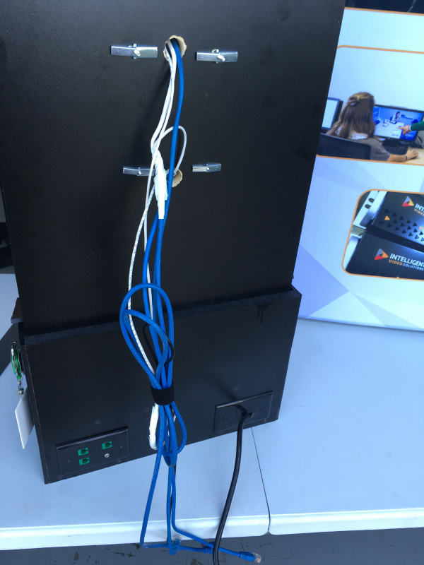
On the back of the VALT POC Camera station, connect the wiring from the cameras to the input panel on the base | On the back of the VALT POC Camera station, connect the wiring from the cameras to the input panel on the base | ||
| − | + | {{img | file = PoCunbox8.jpg | width=600px}} {{img | file = PoCunbox9.jpg | width=450px}} | |
Revision as of 13:58, 11 May 2022
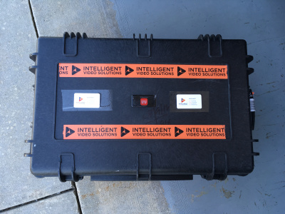
The VALT POC system will be shipped to you in a weather proof hard case. Everything required for you Valt Proof of Concept demonstration will be included in this case.
IVS will only ship the requested equipment for a POC. It may include the following:
- VALT POC Appliance
- VALT POC Camera and Stand
- VALT POC Wireless Access Point
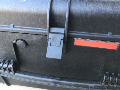
The case will be locked with combination locks. Please contact your VALT Sales Representative for the combination.
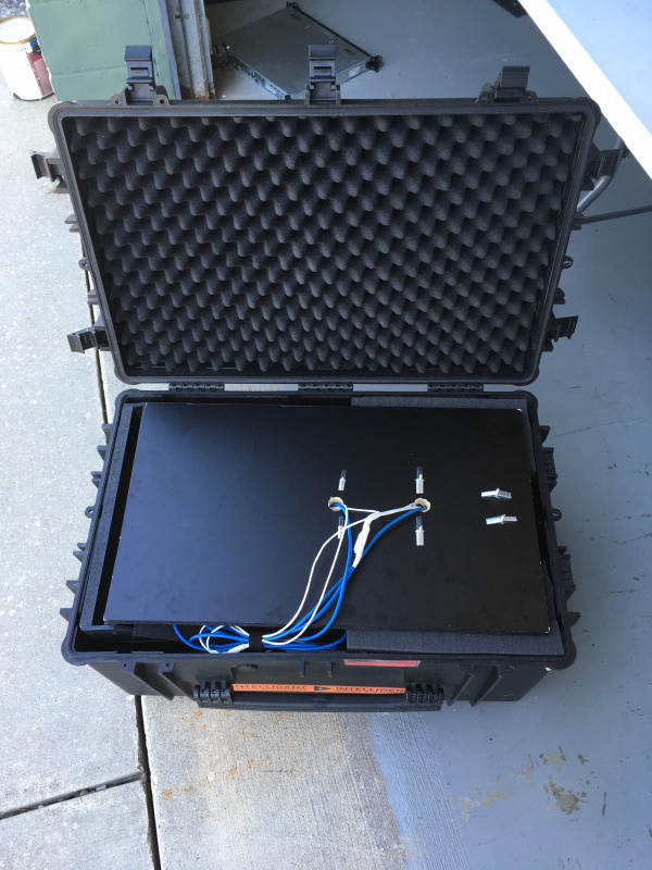
Inside the case, you will find customized foam padding divided into layers. Please make sure to save all padding to use in the return shipment after the proof of concept is complete.
On the top layer will be the back plate VALT POC Camera and Stand
Remove the VALT POC Cameras (back board) and set them aside.
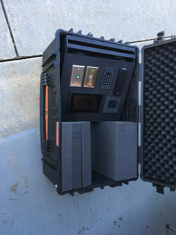
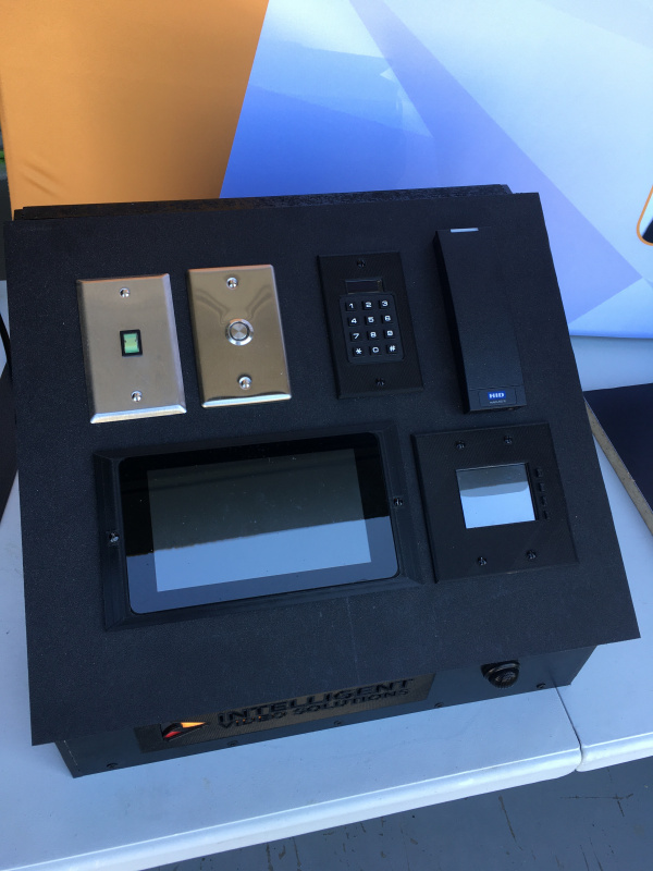
The next element will be the VALT POC Camera base. This houses all wiring, processing, and also contains the accessory panel
Determine an appropriate location for the VALT POC Camera Station
Slide the VALT POC Camera (back board) into the opening into the base of the Stand. The back board should fit snugly.
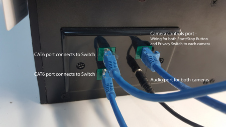
On the back of the VALT POC Camera station, connect the wiring from the cameras to the input panel on the base
