Difference between revisions of "Control Room Audio Solution"
IVSWikiBlue (talk | contribs) |
IVSWikiBlue (talk | contribs) |
||
| Line 37: | Line 37: | ||
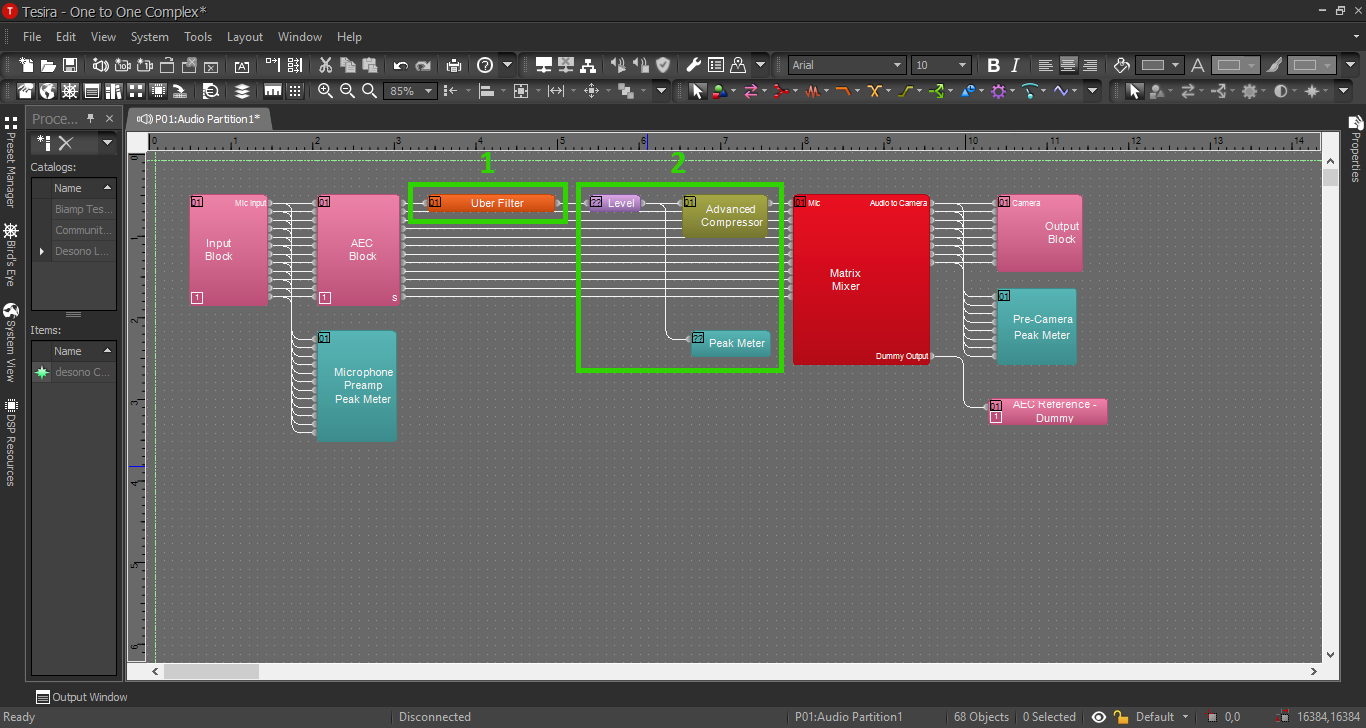
When we're complete, our file should look something like this: | When we're complete, our file should look something like this: | ||
| − | [[File: | + | [[File:CRAS_Config_2.png]] |
Revision as of 12:55, 24 April 2020
Contents
Description/Objective
In this example, we will be building 1 sim rooms with an overhead speaker and 1 observation room with live audio and a talkback microphone. For physical devices, we will have 1 room microphone, 1 camera, 1 OWISP, and 1 PSP speaker (and/or SHM-1 headphone amp).
Physical Wiring/Line Diagram
We will need 2 inputs and 3 outputs. The inputs and outputs should be as follows:
- Input 1: Sim Room Mic
- Input 2: Control Room Talkback Mic
- Output 1: Camera in Sim Room
- Output 2: OWISP in Sim Room
- Output 3: Control Room Speaker/HP Amp

Tesira Software
Connections
- Once we've completed our physical connections, open the Tesira software and build a configuration.
- In this configuration we'll be using the following blocks. Add these blocks to the configuration:
- TesiraFORTE CI block ("per channel" AEC reference mode)
- Peak Meter x 3
- Uber Filter x 2
- Level Block
- Compressor with 2 channels, "ganged mode" and "advanced curve"
- Matrix Mixer with at least 2 inputs and 3 outputs, with 2 extra outputs
- Connect the blocks as follows:
- The Tesira Input block will already be connected to the AEC block, so connect the first peak meter to the Input block also. This will help us to be sure we have the proper levels set on the preamp.
- Connect the AEC block to the Uber Filters.
- Send the Uber Filters to the Level Block.
- Send the Level Block to the Compressor and the second peak meter.
- Send the Compressor to the Matrix Mixer.
- Connect output 1-3 from the mixer to port 1-3 on the Tesira Output block AND to the third peak meter. This way we can make sure to reach the right audio levels before we send it to the cameras.
- Connect the 2 extra outputs from the Matrix Mixer to ports 1&2 on the AEC reference. More on AEC in a minute.
When we're complete, our file should look something like this:

Matrix Mixer for ORAS with Software Talkback

- Phantom Power: We will need phantom power on for our room mics, and proper levels on the preamps.
- AEC: For the first time in our example configurations, we are going to use Acoustic Echo Cancellation. The reason for this is: anytime we have a microphone and a talkback speaker in the same room, there is the opportunity for an echo. If John is in the control room using the software to talk to Steve, who is in the simulation room, the room mic will pick up John's voice from the OWISP, and John will once again hear his own voice in the control room with a short delay. AEC will help us cancel this delayed audio. Enable the AEC feature with this button on the AEC Block.
- Output Channels: 3A highlights the output channels to the devices for the first pair of ORAS rooms; 3B indicates the devices for the second pair; and 3C highlights the AEC reference channels.
Processing Blocks in Tesira
For further insight about the other processing blocks and settings, refer back to the first configuration example, or click the image below:
EQ and Compression
For information on EQ settings and compression, refer to Simple Configuration with EQ and Compression, or click the image below:
How AEC Works

John is in the observation room, using the talkback feature. His audio is what's in danger of being captured and returned to him