Difference between revisions of "Installing an Axis V5914/V5915 with a Sure MX202i Microphone"
IVSWikiBlue (talk | contribs) |
IVSWikiBlue (talk | contribs) (→Connecting the STM-1) |
||
| Line 67: | Line 67: | ||
#:[[File:Phantom PWR STM.JPG|400x300px]] | #:[[File:Phantom PWR STM.JPG|400x300px]] | ||
#Strip the wiring on the PS-24AS revealing the 2 copper wires inside. Connect the copper to the PWR terminals (White striped to +, Solid Black to the other terminal) of the STM-1. | #Strip the wiring on the PS-24AS revealing the 2 copper wires inside. Connect the copper to the PWR terminals (White striped to +, Solid Black to the other terminal) of the STM-1. | ||
| − | #:[[File: | + | #:[[File:Phantom and Power Connected.JPG|400x300px]] |
#Connect 22/2 to the LO-Z OUTPUT terminals (Red to +, Black to -, Bare Wire to Ground) of the STM-1. Ensure you run enough 22/2 cable to your V5914/V5915 | #Connect 22/2 to the LO-Z OUTPUT terminals (Red to +, Black to -, Bare Wire to Ground) of the STM-1. Ensure you run enough 22/2 cable to your V5914/V5915 | ||
| − | #:[[File: | + | #:[[File:File:LO-Z Connected.JPG|400x300px]] |
#Connect the audio cable that is intended for your microphone to the input terminals of the STM-1 (Red to +, Black to -, Common to the common terminal). Using the Velcro that comes with the STM-1, attach the STM-1 to a safe place (preferably keeping it out of sight). | #Connect the audio cable that is intended for your microphone to the input terminals of the STM-1 (Red to +, Black to -, Common to the common terminal). Using the Velcro that comes with the STM-1, attach the STM-1 to a safe place (preferably keeping it out of sight). | ||
#:[[File:Wired with MIC inside of p5414.JPG|400x300px]] | #:[[File:Wired with MIC inside of p5414.JPG|400x300px]] | ||
(NOTE; If there are 2 cameras in the room, duplitcate step 9.1.3 using a long enough cable to get to the 2nd camera. If there are 2 Shure MX202i Microphones, duplicate step 9.1.4.) | (NOTE; If there are 2 cameras in the room, duplitcate step 9.1.3 using a long enough cable to get to the 2nd camera. If there are 2 Shure MX202i Microphones, duplicate step 9.1.4.) | ||
| − | |||
| − | |||
==Connecting and Mounting the Microphone== | ==Connecting and Mounting the Microphone== | ||
Revision as of 10:27, 3 March 2017
Contents
Required Parts And Tools
- Axis V5914/V5915
- RDL STM-1
- XLR-F Pigtail
- Shure MX202i Microphone
- Starbit Security Driver
- Wire Stripper
- 1/2" paddle bit
- 1 blank single gang wall plate
- Toggle Bolts (If mounting to drop ceiling tile)
- Drill bit and drill
- Phillips head drill bit or Phillips head screwdriver
- Small Flat head screwdriver
- Hole Saw
- B Connectors
- Cat5/6 Patch Cable (7ft-15ft recommended)
- 22/2 Gauge Wire
- Fish Tape or Glow Rod
- Wind Screen (Inside MX202i Box)
- Rubber Stopper (Inside MX202i Box)
- 4 pin XLR-M to XLR-M Adapter (Inside MX202i Box)
- 3.5mm Audio Cable
- RDL PS-24AS
Installation Instructions
Drop Ceiling Mount
- WARNING
- The combined weight of the camera and mounting bracket is approximately 1.7 kg (3.7 lb.).
Make sure that the ceiling material is strong enough to support this weight.
- NOTICE
- The ceiling tile should be 5–60mm (0.2–2.4in.) thick.
- Remove the ceiling tile in which the drop ceiling mount is to be fitted.
- Drill a 7 mm (9/32 in) hole in the ceiling tile.
- Remove the tripod screw from the mounting bracket.
- Attach the short end of the threaded rod to the camera and tighten.
- Assemble the camera, ceiling tile and the mounting bracket and tighten the nut.
- Route and connect all cables to the camera.
- Connect the power supply to a mains power outlet (100–240 VAC).
- Install the ceiling tile with the camera mounted on it
Connecting the STM-1
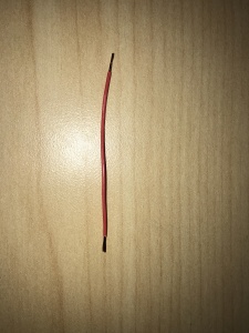
- You will also need to cut a short piece of 22/2 cable (approx. 1 inch). Strip the jacked and from the cable and remove all contents keeping only the red cable. On both ends of the red cable, strip off a piece of the jacked (See picture).
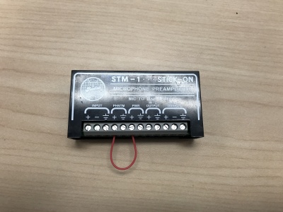
- Connect one end of the 1 inch audio cable to the +PWR terminal and connect the other end of that into the +PHNTM terminal.
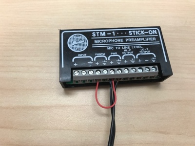
- Strip the wiring on the PS-24AS revealing the 2 copper wires inside. Connect the copper to the PWR terminals (White striped to +, Solid Black to the other terminal) of the STM-1.
- Connect 22/2 to the LO-Z OUTPUT terminals (Red to +, Black to -, Bare Wire to Ground) of the STM-1. Ensure you run enough 22/2 cable to your V5914/V5915
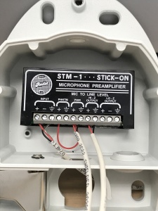
- Connect the audio cable that is intended for your microphone to the input terminals of the STM-1 (Red to +, Black to -, Common to the common terminal). Using the Velcro that comes with the STM-1, attach the STM-1 to a safe place (preferably keeping it out of sight).
(NOTE; If there are 2 cameras in the room, duplitcate step 9.1.3 using a long enough cable to get to the 2nd camera. If there are 2 Shure MX202i Microphones, duplicate step 9.1.4.)
Connecting and Mounting the Microphone
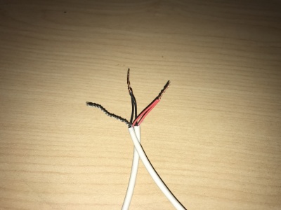
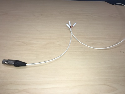
- Strip the jacket of the XLR pigtail revealing the red, black and common cables inside. Strip away a portion of the red and black cables inside the pigtail, revealing the copper wire inside. At the end of your 22/2 cable (not connected to the STM-1), twist the wires together with the pigtail (red to red, black to black, common to common). Secure these with B-Connectors (See Pictures). Repeat this process for 2 microphones.
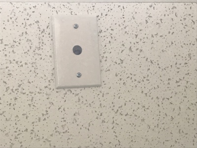
- Using the ½”paddle bit, drill a hole into the center of the single gang plate and a hole into the desired location for the microphone on your drop ceiling tile. Then secure this single gang plate to the desired location of the microphone on your drop ceiling tile using a pair of toggle bolts. Repeat this process for 2 microphones.
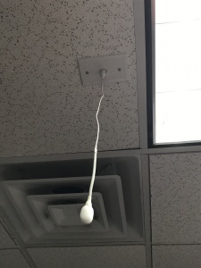
- Run your MX202i through the ½” hole in the ceiling tile and single gang plate. Connect the 4 Pin XLR-F end of the MX202i to the 4 pin XLR-M adapter. Next, connect the XLR-F (that is ran back to the STM-1) to the XLR-M of the adapter. Lastly, use the rubber stopper to plug the ½” hole in the single gang plate.
- Lastly, adjust the length of the cable of the microphone to your desired length, hiding the remainder in the ceiling. Attach the windscreen to the MX202i.


